
Font size
 Worksheets
Pressure Testing and Leak Detection
Total questions: 87
Worksheet time: 44mins
What pressure multiplier is specified for testing the high side of a refrigeration system at 55°C using OFDN?
1.1 times saturation pressure
0.9 times saturation pressure
1.0 times saturation pressure
1.2 times saturation pressure
At what refrigerant temperature is the low side tested to 1.1 times the saturation pressure?
25°C
32°C
45°C
55°C
Which gas must be used to carry out pressure testing for leak checks?
Oxygen Free Dry Nitrogen
Argon
Compressed air
Carbon dioxide
During a bubble test, the system is pressurised with OFDN to which approximate pressure?
300 kPa
200 kPa
150 kPa
100 kPa
Where should the foaming agent be sprayed when performing a bubble test?
Across evaporator fins
Inside the compressor sump
Over brazed joints and flarings
On filter driers only
Which method uses a dye and ultraviolet light to reveal leak locations?
Fluorescent dye trace
Bubble test
Ultrasound test
Electronic test
What indicates a leak during the bubble test?
OFDN turns blue
Temperature rises sharply
Pressure gauge drops suddenly
Foaming agent bubbles up
Which pair correctly lists two alternative non-chemical leak detection methods?
Vacuum decay and soap solution
Electronic test and ultrasound test
Fluorescent dye and bubble test
UV light and tracer gas

In the ATS logo build, what is the specified copper tube size indicated in the diagrams?
1/4 inch tubing size
3/8 inch tubing size
5/16 inch tubing size
1/2 inch tubing size

For the first design, the slanted leg of the letter A forms an angle at the apex. What is that angle?
60 degrees at the apex
45 degrees at the apex
48 degrees at the apex
54 degrees at the apex
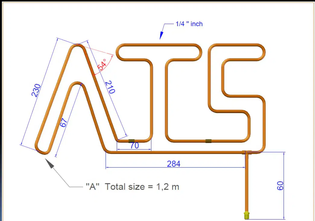
Comparing the three variants, which total assembly length is shown for the first diagram labeled A?
Total size equals 0.8 m
Total size equals 1.2 m
Total size equals 1.0 m
Total size equals 1.5 m
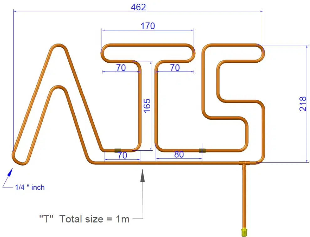
In the second design, what is the horizontal span across the top of the T section?
139 millimeters span
114 millimeters span
170 millimeters span
284 millimeters span
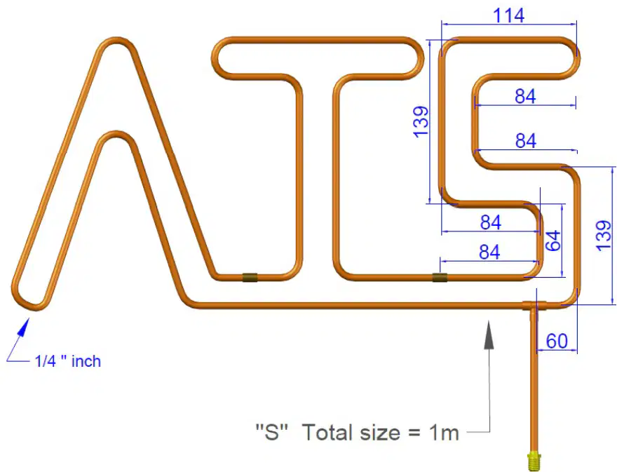
Which dimension appears repeatedly in the third design’s S section bends?
67 millimeters repeats
70 millimeters repeats
84 millimeters repeats
230 millimeters repeats
When purge brazing the assembly, what is the primary purpose of purging with inert gas?
Reduce external heat loss
Strengthen mechanical bends
Prevent internal oxidation scale
Increase filler metal flow rate
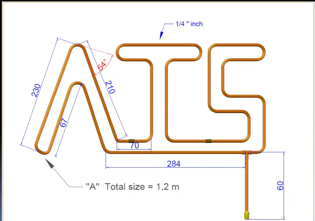
Which measurement defines the vertical drop of the outlet tube at the far right of the first design?
165 millimeters drop
80 millimeters drop
67 millimeters drop
60 millimeters drop
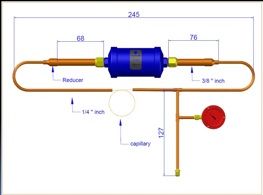
In the first diagram, which tube size is specified for the branch labeled capillary that drops vertically to the pressure gauge tee?
1/4 inch copper tube
3/8 inch copper tube
1/2 inch copper tube
5/16 inch copper tube
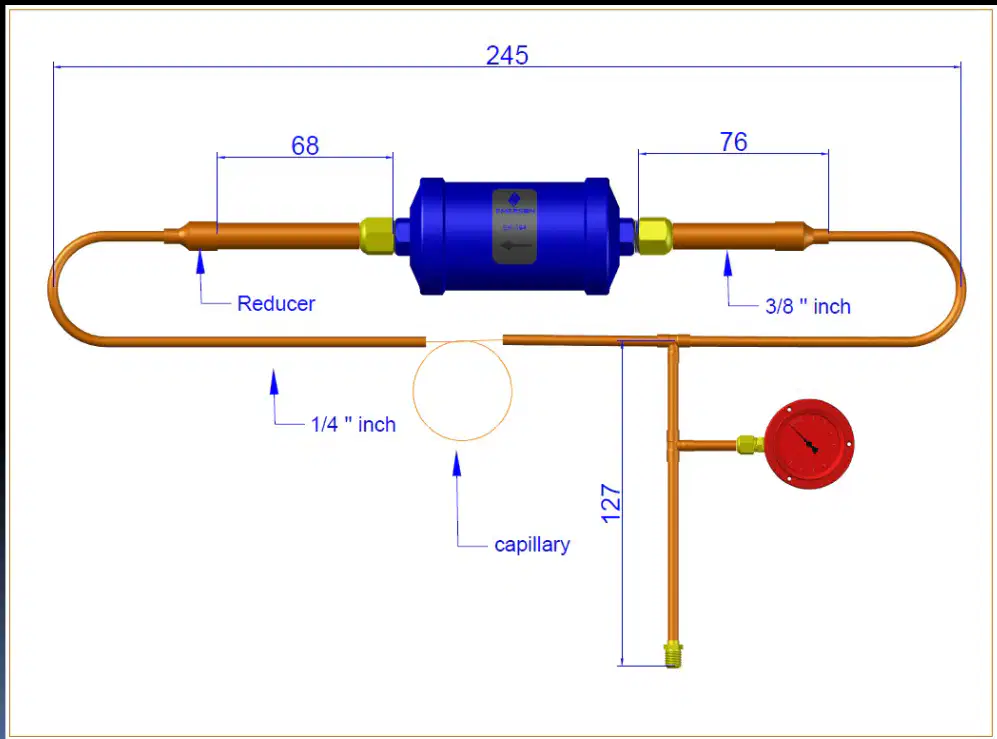
Which component connects the smaller copper tube to the filter-drier body on both diagrams?
Union coupling
Threaded nipple
Reducer fitting
Elbow connector
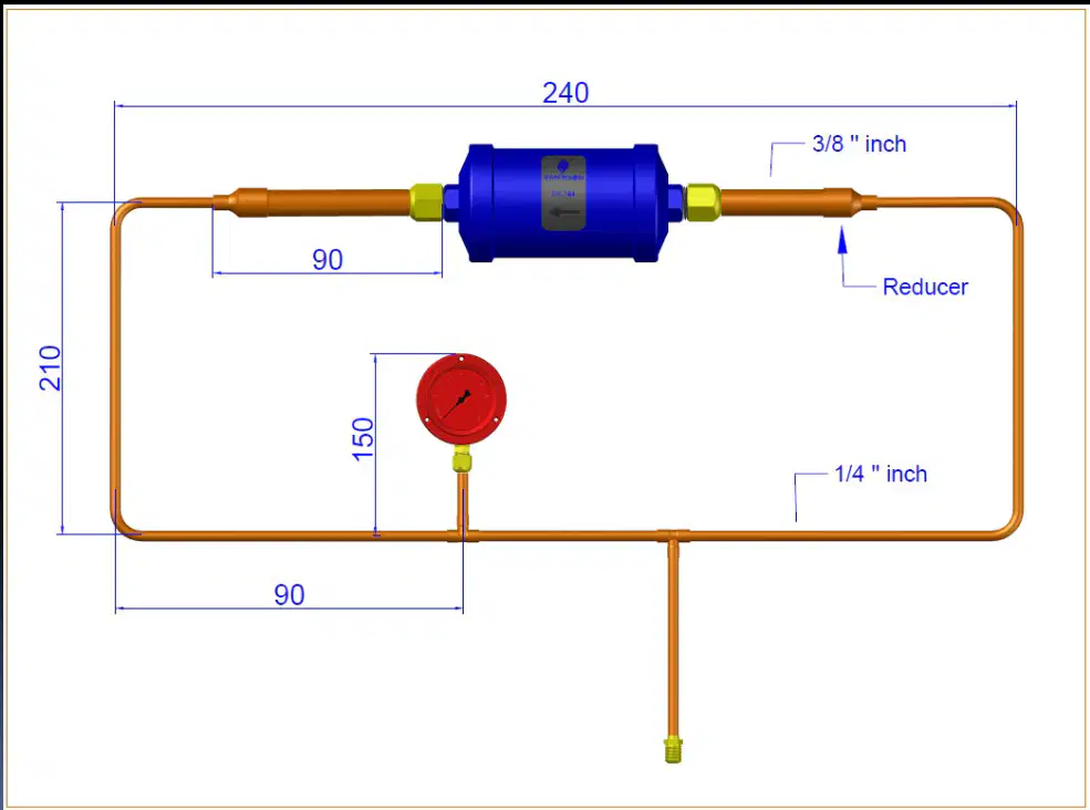
When preparing a flare joint for the 3/8 inch line shown, what is the correct first step before flaring?
Fill the tube with nitrogen
Deburr the cut tube end
Tighten the flare nut fully
Heat the tube end with a torch
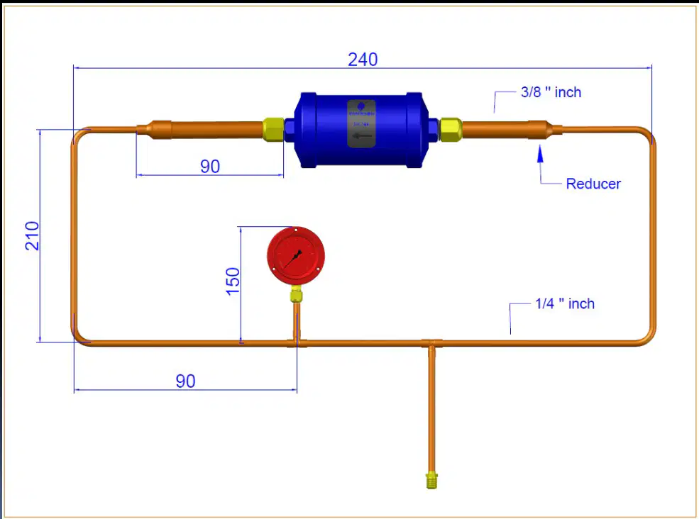
The pressure gauge is integrated via a vertical leg. What planning choice best ensures accurate pressure readings during testing?
Mount gauge after brazing cools
Locate gauge on a dead-end stub
Place gauge upstream of reducer
Install gauge on the capillary outlet

Given the overall length of 245 mm in the first diagram and a straight segment of 76 mm on the right, which action maintains layout accuracy during bending?
Select the smallest radius available
Cut tubes longer than final size
Add bend allowance to measured runs
Ignore bend allowances entirely
What micron level is the target for deep evacuation on new refrigeration systems?
1000 microns target level
100 microns target level
200 microns target level
500 microns target level
Which component measures the vacuum level during evacuation?
Refrigerant manifold gauge
Oil sight glass indicator
Nitrogen regulator unit
Vacuum analyzer device
Before connecting the vacuum pump, what must be ensured about the system sections?
Not connected to pressurised sections
Filled with dry refrigerant
Closed with service caps
Heated to operating temperature
What initial nitrogen test pressure should be released to just above atmospheric?
60 kPa or 10 psi
200 kPa or 30 psi
30 kPa or 5 psi
10 kPa or 2 psi
Which action is performed immediately after starting the vacuum pump?
Break vacuum with nitrogen
Isolate vacuum analyzer
Charge system with OFDN
Open ballast valve slowly
At 1000 microns, what is the next step in triple evacuation?
Isolate analyzer and charge OFDN
Open analyzer to the system
Continue pumping to 200 microns
Break vacuum with refrigerant
How much Oxygen Free Dry Nitrogen is charged at 1000 microns and 500 microns?
50 kPa or 8 psi
300 kPa or 45 psi
100 kPa or 15 psi
200 kPa or 30 psi
Which sequence is repeated during triple evacuation?
Repeat steps 1 through 5
Repeat steps 2 through 9
Repeat steps 6 through 8
Repeat steps 3 through 10
When 200 microns or less is achieved, what should be done?
Charge OFDN once more
Start ballast valve again
Connect to pressurised sections
Isolate pump and analyzer
After isolating at ≤200 microns, how is the system prepared for refrigerant?
Pressurize with compressor oil
Flush with clean refrigerant
Purge with dry air stream
Break vacuum with nitrogen
Which procedure focuses on safely removing liquid refrigerant from a system using a recovery unit and cylinder?
Vapour recovery using suction side only
Liquid recovery with cylinder and manifold
Push-pull recovery without gauges
Pressure testing using nitrogen only
Before starting liquid recovery, what should be done with the recovery cylinder to track the amount recovered?
Record ambient temperature nearby
Place cylinder on scale and zero
Purge manifold set with dry air
Close all service valves firmly
Which port on the recovery cylinder valve assembly should the discharge hose from the recovery equipment connect to for liquid recovery?
The liquid port on cylinder
The service plug on cylinder
The relief port on cylinder
The vapour port on cylinder
Where should the hose from the refrigeration system high-side service port connect during liquid recovery setup?
To high-side port of manifold set
To cylinder vapour port fitting
Directly to recovery machine suction
To low-side gauge on manifold
Which manifold valve positions initiate liquid transfer through the manifold during the process?
Open high-side, close low-side
Close both sides completely
Open low-side, close high-side
Open both sides simultaneously
What is the purpose of connecting a hose from the cylinder vapour port to the high-side gauge on the manifold?
Monitor cylinder pressure safely
Allow purging of recovery unit
Measure ambient humidity
Balance suction and discharge
When all liquid has been removed from the system, which recovery mode should be used next to clear remaining refrigerant?
Start push-pull circulation mode
Begin deep vacuum evacuation
Switch to vapour recovery mode
Continue liquid mode indefinitely
Which connection is made to the suction side of the recovery machine during liquid recovery?
The hose from manifold high-side
The hose from system discharge port
The hose from cylinder liquid port
The hose from manifold low-side
To prevent refrigerant loss at connections, which fitting type is specified on hoses used with recovery equipment?
Compression ferrule coupling
High-flow quick connect
Low loss fitting on each end
Standard barbed adapter
Which step ensures you can calculate how much refrigerant can be stored in the recovery cylinder?
Warm cylinder to room temperature
Weigh cylinder and compute capacity
Purge cylinder with dry nitrogen
Measure cylinder internal volume
During liquid recovery, which valves on the recovery cylinder must be opened before starting the recovery system?
Neither valve until purged
Both liquid and vapour valves
Only vapour valve opened
Only liquid valve opened
Which selector setting on the recovery unit should be chosen to begin transferring liquid refrigerant?
Selector set to liquid
Selector set to vapour
Selector set to vacuum
Selector set to purge
What is the correct connection path for liquid refrigerant leaving the refrigeration system during recovery?
System low-side to cylinder vapour
System high-side through manifold to recovery equipment discharge
System suction to recovery equipment suction
System discharge directly to cylinder relief
Why is the high-side valve on the manifold closed while the low-side valve is opened during liquid recovery?
To prevent cylinder scale drift
To increase ambient airflow
To measure superheat precisely
To direct flow through low-side path
What action should be taken with the recovery unit after setup to avoid cross-contamination before actual recovery?
Cool the cylinder with ice
Run a purge of the recovery unit
Adjust manifold gauges to zero
Bleed air into the cylinder
Which step should be done first in vapour recovery to determine capacity?
Open liquid and vapour valves on cylinder
Connect hose to discharge side of recovery unit
Calculate how much refrigerant can be recovered
Place recovery cylinder on scale and zero
Why is the recovery cylinder placed on a scale and zeroed?
To close the high-side valve on the manifold
To monitor cylinder pressure during operation
To measure refrigerant mass added accurately
To set the manifold selector to vapour mode
Which port on the recovery cylinder receives the hose from the discharge side of the recovery equipment?
Centre port of manifold
Cylinder vapour port on cylinder
Cylinder liquid port on cylinder
Low-side service port of system
Where should the hose from the system’s suction service port be connected?
Low-side port of the manifold
High-side valve of the manifold
Cylinder liquid port
Discharge side of recovery equipment
Which connection allows monitoring of cylinder pressure during vapour recovery?
Hose from suction port to low-side manifold
Hose from discharge side to cylinder liquid port
Hose from cylinder vapour port to high-side valve
Hose from manifold center to system high-side
Before starting the recovery system, which valves on the manifold should be set?
Close both low-side and high-side valves
Open both low-side and high-side valves
Open low-side and close high-side valves
Open high-side and close low-side valves
Which valves must be opened on the recovery cylinder when ready to recover vapour?
Neither liquid nor vapour valves
Both liquid and vapour valves
Vapour valve only
Liquid valve only
What does setting the valve selector to “vapour” achieve?
Configures unit to recover refrigerant as vapour
Routes flow through high-side manifold line
Enables purging between recovery methods
Starts closing all valves after recovery
The recovery unit should pull to an appropriate vacuum based on which factor?
Type of refrigerant being recovered
Length of hoses connected
Age of recovery cylinder
Ambient temperature near equipment
When should recovery be stopped relative to cylinder capacity?
When both manifold valves are closed
When the manifold selector is on liquid
When maximum allowable weight is reached
When cylinder internal pressure equals system
Switching from vapour to liquid recovery may require which action?
Increasing cylinder pressure with nitrogen
Opening only the high-side manifold valve
Changing hose connections and unit purging
Removing the cylinder from the scale
After recovery is complete, what is the correct next step?
Close all valves and disconnect or purge
Open all valves and begin purge cycle
Leave valves open to equalize pressures
Switch the selector to liquid and continue
What is the first step before beginning push-pull refrigerant recovery?
Place cylinder on a scale and zero
Weigh cylinder and calculate recovery
Connect manifold center port to vapor
Open the recovery unit valves
Why should the recovery cylinder be placed on a scale and zeroed?
To prevent hose vibration during flow
To test the sight glass for leaks
To measure net refrigerant transferred
To balance pressures in the manifold
Which manifold port connects to the cylinder vapor port during setup?
Low-side manifold port
High-side manifold port
Center manifold port
Discharge recovery port
If the manifold lacks a sight glass, what is recommended?
Use a larger diameter hoses
Switch to vapor-only recovery
Fit a sight glass to the recovery line
Install a filter drier on suction
Where should a hose from the manifold low-side be connected?
Recovery unit discharge side
Recovery cylinder vapor valve
Recovery unit suction side
System high-side service port
Which connection uses low loss fittings on both ends from the recovery unit discharge?
To recovery cylinder liquid valve
To manifold center port
To recovery unit suction side
To system high-side service port
Before moving refrigerant, what must be done to the recovery cylinder valves?
Throttle valves to half open
Close all valves on manifold set
Purge air using the sight glass
Open the valves on recovery cylinder
When should the refrigerant recovery unit be started?
After the scale shows weight gain
After opening recovery cylinder valves
Before any hoses are connected
After switching to vapor recovery mode
Which manifold valve is opened after starting the recovery unit?
Cylinder liquid valve
High-side manifold valve
Center port isolation valve
Low-side manifold valve
What parameter must be monitored throughout push-pull recovery?
System superheat value
Ambient temperature near unit
Sight glass color indicator
Scale reading on cylinder
What indicates it is time to switch the unit to vapor recovery?
Cylinder temperature rises slightly
Scale stops picking up weight
Manifold pressure exceeds setpoint
Sight glass shows bubbles persist
Switching to vapor recovery requires what change?
Cylinder must be swapped out
Manifold gauges must be replaced
Scale must be recalibrated again
Hose connections must be changed
What is the purpose of using low loss fittings in this method?
Reduce scale measurement error
Improve sight glass visibility
Increase cylinder internal pressure
Prevent refrigerant leakage at hoses
Which item must appear on a system data plate to uniquely identify a unit?
Refrigerant class notation
Model or type designation
Manufacturer’s name and logo
Serial number identifier
What information on the data plate specifies the working fluid used in the system?
R.P.M. and oil type
Refrigerant type indicated
Test pressure rating
Open drive or pump type
Which data plate entry defines the quantity of refrigerant mixture components?
Mass of refrigerants listed
Model or type number
Manufacturer’s name printed
Serial number sequence
Which parameter on the data plate relates to mechanical speed and lubricant specification?
Open drive or pump type
Refrigerant category
R.P.M. and oil type
Test pressure limit
Before charging, what must be ensured about the service valves on the receiver and metering device?
Fully open to purge air
Shut to block trapped air
Set to mid-position
Bypassed using a tee
Where does the HP (red) pressure gauge connect during charging setup?
Discharge line of compressor
Service port on refrigerant receiver
Service port on service valve
Liquid valve on cylinder
The LP (blue) gauge connects to which point in the system during setup?
Service port on service valve
Outlet of receiver tank
Cylinder vapor valve
Liquid line solenoid body
Why is a magnet placed on the solenoid valve during charging preparation?
To calibrate pressure gauges
To seal the LP gauge port
To keep the solenoid valve open
To mark liquid line direction
For first-time charging, which hose connects to the cylinder’s liquid (red) valve?
Blue hose from LP gauge
Yellow hose from manifold
Red hose from HP gauge
Green hose from recovery
When removing trapped air from hoses during initial charge, which valve is opened first?
HP gauge then LP gauge
Cylinder red liquid valve
LP gauge then HP gauge
Service valve by receiver
After pressurizing the hoses, what is the correct sequence with the gauges to bleed air?
Open HP and LP simultaneously
Close both, open service valve
Open LP, close LP, open HP
Open HP, close HP, open LP
During recharge after recovery, which components remain sealed indicating no air in those lines?
Receiver outlet sealed
HP and LP gauges sealed
Yellow hose sealed
Service valve sealed
In a recharge after recovery, where is trapped air likely present and needs bleeding?
In the yellow service hose
Inside the receiver tank
At the solenoid coil body
Within the compressor head
How do you pressurize the yellow hose to purge air during recharge?
Open service valve port
Open compressor discharge
Open LP gauge valve
Open cylinder red valve
Which data plate detail informs whether the machine uses open drive or pump configuration?
Open drive or pump type
Serial number code
Test pressure label
Refrigerant listing
What does the test pressure entry on a data plate primarily indicate?
Maximum allowable working pressure
Operating temperature limits
Electrical supply requirements
Compressor displacement value
Which visual indicator in a sight glass suggests proper liquid charging flow during operation?
Clear liquid without bubbles
Continuous bubbles present
Foam forming at outlet
Milky appearance in glass

