
 Worksheets
Fuel Oil (week 15)
Total questions: 58
Worksheet time: 10mins
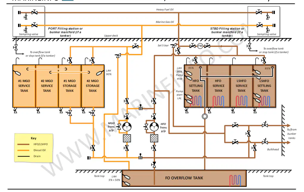
Identify the diagram.
Fuel Oil Storage System
Fuel Oil Bunkering/ Transfer System
Fuel Oil Purification System
Fuel Oil Service System (Booster System)
Engine Fuel Injection System
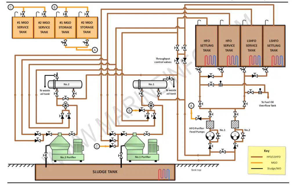
Identify the diagram.
Fuel Oil Return System
Engine Fuel Injection System
Fuel Oil Service System (Booster System)
Fuel Oil Purification System
Fuel Oil Transfer System
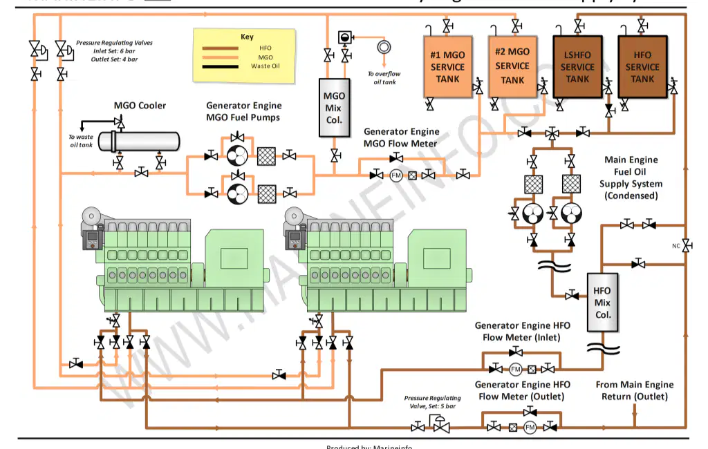
Identify the diagram.
Auxiliary Engine Fuel Oil Service System
Engine Fuel Injection System
1.Fuel Oil Bunkering System
Fuel Oil Storage System
Fuel Oil Transfer System
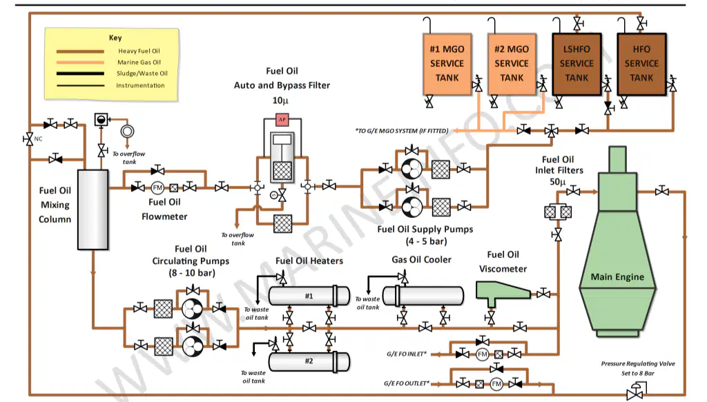
Identify the diagram.
Main Engine Fuel Oil Service System
Engine Fuel Injection System
Fuel Oil Transfer System
Fuel Oil Transfer System
Fuel Oil Purification System
When parameters of fuel oil exceed manufacturer limits, it can cause:
Engine performance issues
Component wear
Reduced emissions
Safety hazards
Parameter: Water content
Out-of-limit Condition: < 0.5%
Corrective Action: Enhance separation, drain tank bottoms, increase purifier throughput
True
False
Parameter: Viscosity
Out-of-limit Condition: Too high/low
Corrective Action: ________
Adjust fuel heating temperature to achieve correct injection viscosity
Enhance separation, drain tank bottoms, increase purifier throughput
Increase purifier retention time, replace filters frequently
Switch to compliant fuel or install scrubbers
Reject fuel for marine use or blend with higher flash point fuel
Parameter: Cat fines (Al+Si)
Out-of-limit Condition: __________
Corrective Action: Increase purifier retention time, replace filters frequently
> 15 ppm
< 15 ppm
> 0.5%
Too high/low
Safety hazard
Parameter: _________
Out-of-limit Condition: Beyond ECA limits (0.1%)
Corrective Action: Switch to compliant fuel or install scrubbers
Sulfur content
Flash point < 60°C
Density mismatch
Viscosity
Cat fines (Al+Si)
Parameter: Density mismatch
Out-of-limit Condition: High density beyond purifier setting
Corrective Action: ____________
Adjust purifier gravity disc or use automated gravity disc
Switch to compliant fuel or install scrubbers
Reject fuel for marine use or blend with higher flash point fuel
Enhance separation, drain tank bottoms, increase purifier throughput
Adjust fuel heating temperature to achieve correct injection viscosity
Parameter: Flash point < 60°C
Out-of-limit Condition: Safety hazard
Corrective Action: Reject fuel for marine use or blend with higher flash point fuel
True
False
A scrubber is a pollution control device used on ships to remove harmful components—primarily sulfur oxides (SOₓ)—from exhaust gases produced by burning fuel oil, especially MDO/MGO.
True
False
Open-Loop Scrubber: Uses freshwater mixed with an alkaline chemical (like caustic soda) to clean exhaust gases. The water is recirculated, and only a small amount of waste is discharged.
True
False
Uses seawater to wash exhaust gases. The water absorbs SOₓ and is then discharged back into the sea after treatment.
Open-Loop Scrubber
Closed-Loop Scrubber
Hybrid Scrubber
Hybrid Scrubber
Can operate in both open and closed modes depending on environmental regulations and water availability.
Uses freshwater mixed with an alkaline chemical (like caustic soda) to clean exhaust gases. The water is recirculated, and only a small amount of waste is discharged.
Uses seawater to wash exhaust gases. The water absorbs SOₓ and is then discharged back into the sea after treatment.
Purpose of a Scrubber:
To comply with IMO 2020 regulations, which limit sulfur content in marine fuels to 0.50% m/m (mass by mass).
To allow vessels to continue using cheaper high-sulfur fuel oil (HSFO) by cleaning the exhaust gases before release into the atmosphere.
Meet Environmental Regulations: Scrubbers enable vessels and industries to meet strict environmental standards and avoid penalties.
Control Particulate Emissions: Scrubbers help trap and remove soot, ash, and other fine particles from exhaust gases, improving air quality.
Improve Fuel Quality: By purifying fuel oil, the system ensures better combustion, increasing engine efficiency and reducing emissions.
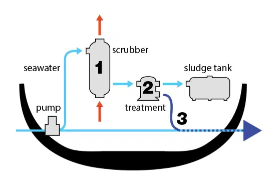
Identify the scrubber diagram.
Open-Loop Scrubber
Closed-Loop Scrubber
Hybrid Scrubber
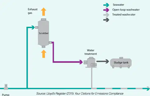
Identify the scrubber diagram.
Open-Loop Scrubber
Closed-Loop Scrubber
Hybrid Scrubber
Treatment Method and Chemicals
Method: Heating
Purpose: Reduce viscosity for better flow
How It Works: ___________
Fuel is heated using heaters (steam or electric) to improve pumpability and atomization.
Time-based gravity separation in tanks before further purification.
A high-speed centrifuge separates fuel into layers: clean oil, water, and sludge.
Fuel passes through filters (coarse & fine) to trap solid contaminants.
Fuel oil treatment is essential to ensure clean, efficient combustion and protect engine components. It involves both physical and chemical methods to remove contaminants like water, solids, and harmful chemicals.
True
False
Treatment Method and Chemicals
Method: Settling Tanks
Purpose: ________
How It Works: Time-based gravity separation in tanks before further purification.
Allow heavy particles and water to settle
Remove water and solids
Remove fine particles
Reduce viscosity for better flow
Keep sludge and particulates suspended
Treatment Method and Chemicals
Method: Clarifying
Purpose: Remove water and solids
How It Works: A high-speed centrifuge separates fuel into layers: clean oil, water, and sludge.
True
False
Treatment Method and Chemicals
Method: ________
Purpose: Remove fine particles
How It Works: Fuel passes through filters (coarse & fine) to trap solid contaminants.
Filtering
Settling Tanks
Centrifuging
Heating
Treatment Method and Chemicals
Method: Service Tanks
Purpose: Allow heavy particles and water to settle
How It Works: Time-based gravity separation in tanks before further purification.
True
False
Treatment Method and Chemicals
Chemical: Demulsifiers
Purpose: Break water-fuel emulsions
How It Works: Help coalesce and separate water from fuel for easier removal by centrifuges.
True
False
Treatment Method and Chemicals
Chemical: Dispersants
Purpose: Prevent oxidation and gum formation
How It Works: Prevents sludge from settling or clogging filters by keeping them dispersed.
True
False
Treatment Method and Chemicals
Chemical: ___________
Purpose: Protect engine and tank surfaces
How It Works: Form protective films on metal surfaces to reduce acid and water corrosion.
Corrosion Inhibitors
Biocides
Cat Fine Dispersants
Combustion Improvers
Treatment Method and Chemicals
Chemical: Biocides
Purpose:_________________
How It Works: Prevents microbial corrosion and clogging of lines from sludge buildup.
Kill microbial growth in water-fuel layers
Protect engine and tank surfaces
Enhance combustion efficiency and reduce emissions
Prevent abrasive catalyst fines from settling
Choose all the Fuel Oil Mechanical Treatment Method:
Heating
Storage Tanks
Centrifuging
Filtering
Stabilizing
Choose all the Chemicals for Fuel Oil Treatment :
Cat Fine Dispersants
Combustion Improvers
Corrosion Inhibitors
Biocides
Nitrite
Safety in Handling Chemicals
Personal Protective Equipment (PPE). (choose all the appropriate PPE when dealing with chemicals)
Safety goggles
FIre-resistant gloves
Long-sleeved coveralls
Respirator (if needed)
Safety boots (non-slip)
Safety in Handling Chemicals
Chemical Storage – Engine Room & Chemical Locker: (choose all the appropriate guidelines)
Store in designated chemical lockers
Secure containers properly
Avoid stacking incompatible chemicals
Ensure proper labeling
Safety in Handling Chemicals
Handling and Dosing Procedures (choose all the answers)
Follow manufacturer and SDS instructions
Use dedicated dosing pumps or containers
Never mix chemicals randomly
Add water to chemical (not vice versa)
Safety in Handling Chemicals
Waste Handling & Environmental Safety:
Step: Never discharge chemical waste overboard
Onboard Action: Use waste oil tank or designated chemical waste drums
True
False
Overdosing treatment chemicals can be as harmful as underdosing—follow dosing charts strictly.
True
False
How a Centrifugal Separator Works
Separation by Density:
1.Lightest: Sludge/solids (e.g., cat fines) pushed to the bowl wall.
2.Medium: Water forms a ring closer to the center.
3.Heaviest: Clean fuel collects near the axis and is discharged.
True
False
Centrifugal Separators (Purifiers)
Key Components
Component: Heater
Function: Reduces fuel viscosity
True
False
Centrifugal Separators (Purifiers)
Key Components
Component: Inlet/Outlet Ports
Function: ______________
Feed and discharge paths
Reduces fuel viscosity
Provides centrifugal force
Ejects accumulated solids
Manages automation and alarms
Centrifugal Separators (Purifiers)
Key Components
Component: __________________
Function: Provides centrifugal force
Rotating Bowl
Heater
Gravity Disc
Control Panel
Inlet/Outlet Ports
Centrifugal Separators (Purifiers)
Key Components
Component: Gravity Disc
Function: Sets the fuel-sludge interface
True
False
Centrifugal Separators (Purifiers)
Key Components
Component: Sludge Ports
Function: _______________
Ejects accumulated solids
Manages automation and alarms
Provides centrifugal force
Reduces fuel viscosity
Centrifugal Separators (Purifiers)
Key Components
Component: Control Panel
Function: Manages automation and alarms
True
False
Centrifugal Separators (Purifiers)
Operational Adjustments: (choose all the appropriate answers)
Adjust gravity disc size based on fuel density
Maintain correct feed rate
Preheat fuel to correct separation temperature (usually 98–105°C for HFO)
Clean disc stack and bowl regularly
Centrifugal Separators (Purifiers)
Out-of-limit parameters like high cat fines, high water content, or increased sludge formation will require: (choose all the answers)
More frequent cleaning
Slower throughput for better separation
Enhanced filtration post-separation
Decreased heating
Fuel Blending:
•Involves mixing two or more fuel types to achieve desired properties:
Adjusting viscosity
Lowering sulfur content
Enhancing flash point
Ensuring compatibility
Fuel Blender and Alternative Fuel Treatments
Key Parameters Controlled During Blending
Parameter: Sulfur Content
Why It Matters: Must comply with IMO regulations (0.50% global, 0.10% in ECAs).
True
False
Fuel Blender and Alternative Fuel Treatments
Key Parameters Controlled During Blending
Parameter: Flash Point
Why It Matters: Must be <60°C as per SOLAS (safety requirement to prevent fire hazards).
True
False
Fuel Blender and Alternative Fuel Treatments
Key Parameters Controlled During Blending
Parameter: Viscosity
Why It Matters: _______
Needs to match engine injection and atomization specifications (e.g., 10–20 cSt).
Affects separator settings and combustion efficiency.
Must be ≥ 60°C as per SOLAS (safety requirement to prevent fire hazards).
Must comply with IMO regulations (0.50% global, 0.10% in ECAs).
Fuel Blender and Alternative Fuel Treatments
Key Parameters Controlled During Blending
Parameter: ______________
Why It Matters: Affects separator settings and combustion efficiency.
Density
Viscosity
Compatibility
Flash Point
Sulfur Content
Fuel Blender and Alternative Fuel Treatments
Key Parameters Controlled During Blending
Parameter: Compatibility
Why It Matters: Prevents sludge formation when mixing different fuels.
True
False
Fuel Blender and Alternative Fuel Treatments
Chemical Additives Used
Additive: Biocides
Purpose: ___________________
Prevent microbial growth in bio-blends and distillates
Enhance ignition quality and reduce emissions
Extend storage life of fuels like biofuels
Prevent stratification and sludge
Fuel Blender and Alternative Fuel Treatments
Chemical Additives Used
Additive: _________________
Purpose: Enhance ignition quality and reduce emissions
Combustion improvers
Antioxidants
Compatibility agents
Stabilizers
Fuel Blender and Alternative Fuel Treatments
Chemical Additives Used
Additive: Compatibility agents
Purpose: Reduce risk of incompatibility between fuel types
True
False
Fuel Blender and Alternative Fuel Treatments
Proper Blending and Treatment Ensure:
Benefit: Regulatory Compliance
Explanation: Meets IMO sulfur caps, carbon intensity (CII), and emissions limits
True
False
Fuel Blender and Alternative Fuel Treatments
Proper Blending and Treatment Ensure:
Benefit: Correct Viscosity and Flash Point
Explanation: __________
Ensures safe combustion and compliance with SOLAS (>60°C flash point)
Avoids sludge formation and filter clogging from incompatible fuels
Prevents injector damage, pump wear, and combustion knock due to poor fuel mix
Meets IMO sulfur caps, carbon intensity (CII), and emissions limits
Fuel Blender and Alternative Fuel Treatments
Proper Blending and Treatment Ensure:
Benefit: __________
Explanation: Avoids sludge formation and filter clogging from incompatible fuels
Fuel Stability & Compatibility
Regulatory Compliance
Correct Viscosity and Flash Point
Engine Reliability
Fuel Blender and Alternative Fuel Treatments
Proper Blending and Treatment Ensure:
Benefit: Water and Cat Fine Removal
Explanation: Improves ignition quality and reduces soot, smoke, and fuel consumption
True
False
Fuel Blender and Alternative Fuel Treatments
Proper Blending and Treatment Ensure:
Benefit: Optimized Fuel Cost
Explanation: Enables use of blended fuels to balance cost and quality
True
False

