
Font size
 Worksheets
FILL IN THE BLANKS PRACTICE TEST - IE
Total questions: 69
Worksheet time: 43mins
Choose power switches used in controlled rectifier circuits.
BJTs
Diodes
IGBTs
Thyristors
SCR is defined as ...............
Silicone Cup Rectifier
Supply Controlled Rectifier
Silicone Controlled Rectifier
Shorted Controlled Rectifier
Which is the symbol of SCR?


Terminals of SCR are ..........
Anode and Cathode
Collector, Base and Emitter
Anode, Cathode and Gate
Drain, Source and Gate
Power Electronics can be defined as ...........
A conversion from Alternating Current to Direct Current of Power Supply
A conversion of DC power supply to AC power supply
A conversion of AC power supply to AC power supply
A technology of converting electric power from one supply to another supply using electronic power devices.
The electronic devices below are unidirectional devices EXCEPT:
TRIAC
Diode
Silicone Controlled Rectifier
A silicon controlled rectifier (SCR) is a_______
Unijunction device
Device with three junction
Device with four junction
None of the above
A thyristor is basically_____
PNPN device
A set of SCRs
A combination of diac and triac
A set of SCR, diac and a triac
To switch on SCR need ......
Positive Vgt
Negative Vgt
Base current
Collector current
Which of the following statement is correct for an SCR operating in REVERSE BLOCKING MODE - practical condition
What is the basic principle of operation of an SCR?
The basic principle of operation of an SCR is to control current flow by using a gate signal to switch it on, and it remains on until the current falls below a certain level.
The SCR can only be turned off by removing the power supply completely.
An SCR operates by allowing current to flow continuously without any control signal.
An SCR functions by amplifying the input signal to control the output current.
How does the gate terminal influence the conduction of an SCR?
The gate terminal controls the conduction state of an SCR by allowing it to turn on at lower voltages when a positive gate voltage is applied.
The gate terminal prevents the SCR from turning on at any voltage.
The gate terminal is used to control the current flowing through the SCR.
The gate terminal only affects the reverse bias of the SCR.
What is the maximum voltage rating of a typical SCR?
Up to 5,000 volts
Up to 3,000 volts
Up to 10,000 volts
Up to 1,000 volts
What is the significance of the holding current in an SCR?
The holding current is the maximum current an SCR can handle before turning off.
The holding current is significant as it determines the minimum current required to keep the SCR in the on state.
The holding current is the voltage required to trigger the SCR.
The holding current is irrelevant to the operation of an SCR.
Explain the term 'phase control' in the context of controlled rectifiers.
Phase control refers to the process of synchronizing multiple rectifiers.
Phase control is a technique used in controlled rectifiers to adjust the output voltage by varying the firing angle of the thyristors.
Phase control is a method for converting AC to DC without any regulation.
Phase control is used to increase the frequency of the output signal.
What are the advantages of using a controlled rectifier?
Limited control over output voltage
Higher power losses
Advantages of using a controlled rectifier include precise control of power, improved efficiency, reduced power losses, and cost-effectiveness.
Increased complexity in design
How does a controlled rectifier differ from an uncontrolled rectifier?
A controlled rectifier is always more efficient than an uncontrolled rectifier.
A controlled rectifier can regulate output using a gate signal, while an uncontrolled rectifier operates without control.
An uncontrolled rectifier can be turned on and off using a gate signal.
Both types of rectifiers require a constant input voltage to function.
What are the main components of a controlled rectifier?
Diodes, capacitors, inductors
Transformers, resistors, fuses
Microcontrollers, sensors, relays
Power source, load, thyristors (SCRs)
What is the significance of the firing angle in controlled rectifiers?
The firing angle determines the frequency of the output current.
The firing angle controls the output voltage and power in controlled rectifiers.
The firing angle is only relevant in AC circuits.
The firing angle has no effect on the output voltage.
What are the common types of controlled rectifiers?
Inductor
Silicon Controlled Rectifier (SCR), Triac, Diac, Gate Turn-Off Thyristor (GTO)
Transistor
Capacitor
SCR is a ……………….. controlled device
Voltage
Current
Voltage as well as current
None of the above
An SCR is turned off when …………..
Gate is reverse biased
Gate voltage is reduced to zero
Anode current is reduced to zero
None of the above
1) The Main Difference between SCR and SCS in?
a)Gate Terminal
b)Anode Terminal
c)Cathode Terminal
d)Base Terminal

Above symbol is of--------
DIAC
GTO
UJT
TRIAC
IGBT is a combination of Bipolar Junction Transistor (BJT) and
SCR
UJT
FET
MOSFET
A TRIAC is_______
3 terminal bidirectional switch
3 terminal bilateral switch
2 terminal switch
2 terminal bilateral switch
A Triac has three terminals viz ……………
Drain, source, gate
Anode 1, Anode 2 terminal
Cathode, anode, gate
Cathode 1, Cathode 2 and Gate

Identify the structure
TRIAC
SCR
DIAC
GTO

IDENTIFY THE CHARA
SCR
TRANSISTOR
GTO
TRIAC
A triac can pass a portion of …………… half-cycle through the load
Only positive
Only negative
Both positive and negative
depends on the load
In a thyristor circuit, the angle of conduction is changed by changing______
Anode voltage
Gate current
Forward current
Anode current

For a thyristor shown is
All the 3 junctions are forward Biased
J1, J2 are forward biased and j3 reversed biased
J1 is forward biased, J2, J3 reversed biased
J1, J2 are reversed biased J3 is forward biased
Which of the following device incorporates a terminal for synchronizing purposes?
Diac
Triac
Silicon Unilateral Switch (SUS)
None of the above
A SCR is a ________ switch
One directional
Two directional
Three directional
Four directional
di/dt protection is provided to the thryistor by
connecting an inductor in parallel across the load
connecting an inductor in series with the load
connecting an inductor in parallel across the gate terminal
connecting an inductor in series with the gate
The dv/dt protection is provided in order to
limit the power loss
reduce the junction temperature
avoid accidental turn-on of the device
avoiding sudden large voltage across the load
dv/dt protection is provided to the SCR by
connecting a capacitor in parallel with the load
connecting an inductor in series with the load
connecting a capacitor & resister in parallel with the device
connecting an inductor & resister in parallel with the device
Thyristors are used in electronic crowbar protection circuits because it possesses
high surge current capabilities
high amp 2-sec rating
less switching losses
voltage clamping properties
The GTO can be turned off
by a positive gate pulse
by a negative gate pulse
by a negative anode-cathode voltage
by removing the gate pulse
The TRIAC can be represented by
two SCRs in anti-parallel
two SCRs in parallel
two diodes in anti-parallel
two diodes in parallel
The dv/dt protection is provided in order to
limit the power loss
reduce the junction temperature
avoid accidental turn-on of the device
avoiding sudden large voltage across the load
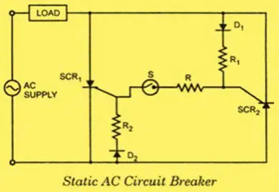
Specify the use of R1 and R2 in the given circuit
Choppers converter
AC to DC
DC to AC
DC to DC
AC to AC
A chopper may be thought as a
Inverter with DC input
DC equivalent of an AC transformer
Diode rectifier
DC equivalent of an induction motor
A step - down choppers can be used in
Electric traction
Electric vehicles
Machine tools
All of these
A step-down chopper is also called as a
first-quadrant chopper
second-quadrant chopper
third-quadrant chopper
fourth-quadrant chopper
The type-C chopper or two quadrant type-A chopper has
type-A and type-B choppers in series
type-A and type-B choppers in parallel
two type-A choppers in series
two type-A choppers in parallel
A type E chopper consists of __________ diodes and _________ switches in anti-parallel.
2, 2
3, 3
4, 4
3, 4

Identify the given circuit
type D chopper
Two quadrant type C chopper
type E chopper
type F chopper
A type C chopper can operate in
Ist and IInd quadrants
IInd and IIIrd quadrants
Ist, IInd and IIIrd quadrants
four quadrants

For a type E chopper, when CH2 is first on and then switched off then the
power flows from source to load
power flows from load to source
load is short circuited
none of the mentioned
In PWM control , ________ parameter is constant
frequency
turn on time
turn off time
none
In PWM control , _________ parameter is variable.
frequency
turn on time
turn off time
none

In the below shown voltage commutated chopper circuit, the chopper operation can only start when
t1 is gated
the capacitor is charged
the diode is forward biased
the capacitor is dis-charged
In pulse width modulation scheme, _________ is kept constant.
Vs
Ton
T
Toff
In a voltage commutated SCR, the main SCR is commutated by
triggering the auxiliary SCR
sending a negative pulse to the main SCR
removing the supply Vs
none of the mentioned
The process of commutating a SCR by applying a reverse voltage to an SCR through a previously charged capacitor is called as
capacitor commutation
forced commutation
voltage commutation
current commutation
whic of the chopper is ideal for DC motor speed control?
Jones Chopper
Morgan Chopper
Class E chopper
Class D chopper

Identify the circuit
Voltage commutated chopper
current commutated chopper
morgan chopper
jones chopper
The load commutated chopper circuit consists of
two thyristors and one commutating capacitor
four thyristors and one commutating capacitor
two thyristors and two commutating capacitors
four thyristors and two commutating capacitors
What is the duty cycle of a chopper ?
Ton/Toff
Ton/T
T/Ton
Toff x Ton

