
 Worksheets
AC Multi-Loop Circuit Analysis Worksheet
Total questions: 99
Worksheet time: 50mins
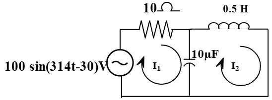
Exercise 1: In Fig.4.1, R, L, C elements are excited by an independent AC voltage source. Which of the following represents the correct KVL equation for mesh-1?
V = I1R + jωL I1 + (I1 - I2) (1/jωC)
V = I1R + jωL I2 + (I1 - I2) (1/jωC)
V = I2R + jωL I1 + (I2 - I1) (1/jωC)
V = I1R + jωL I1 + (I2 - I1) (1/jωC)
Step-1: Calculate the RMS value of the AC voltage source if Vm = 100 V. Fill in the blank: VRMS = ______ V.
70.71 V
50.00 V
100.00 V
141.42 V
Step-2: Represent the AC voltage source in the polar form. Fill in the blank: VRMS = ______
70.71∠−30° V
50∠0° V
100∠−45° V
70.71∠30° V
What is the frequency of the AC source in Hertz (Hz) if ω = 2πf = 314 rad/sec? Fill in the blank: f = ______ Hz.
50 Hz
100 Hz
25 Hz
314 Hz
Step-4: Convert inductance 0.5H to its inductive reactance XL. Fill in the blank: XL = ______ Ω.
157 Ω
79 Ω
314 Ω
50 Ω
Step-5: Convert capacitance 10μF to its capacitive reactance XC. Fill in the blank: XC = ______ Ω.
318.47 Ω
100 Ω
31.85 Ω
3.18 Ω

What are the values of VRMS, XL, and XC used in the circuit?
VRMS = 70.71∠30°, XL = 157 Ω, XC = 318.5 Ω
VRMS = 50∠45°, XL = 200 Ω, XC = 150 Ω
VRMS = 100∠0°, XL = 120 Ω, XC = 220 Ω
VRMS = 60∠60°, XL = 180 Ω, XC = 300 Ω

Step-7: Write the KVL equation for mesh-1 (abefa) in Fig.4.2. Fill in the blank: (10 − j318.5)I1 + j318.5I2 = ______
70.71∠−30°
100∠45°
50∠0°
120∠−60°
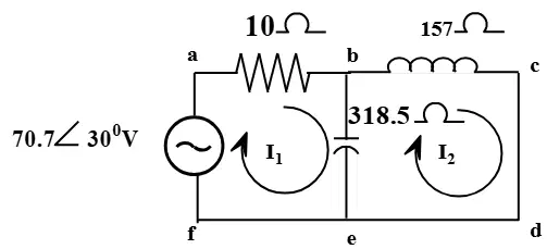
Step-8: Write the KVL equation for mesh-2 (bcdeb) in Fig.4.2. Fill in the blank: j318.5I1 − (j161.5)I2 = ______
0
j157.5I2
j318.5I2
j161.5I1
Step-9: Put the mesh equations in matrix form. Fill in the blank: [10 − j318.5 j318.5; j318.5 −j161.5][I1; I2] = [______; 0]
70.71∠−30°
50∠45°
100∠0°
30∠−60°
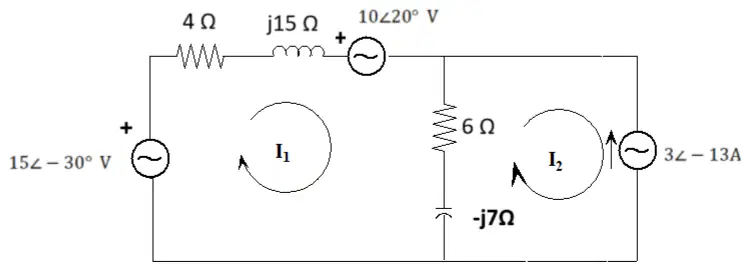
Determine mesh currents I1 and I2 for the network shown in Fig 4.3 using mesh analysis. What is the value of I1?
I1 = 0.227∠61.30° A
I1 = 0.500∠45.00° A
I1 = 0.100∠30.00° A
I1 = 0.350∠75.00° A

Determine mesh currents I1 and I2 for the network shown in Fig 4.3 using mesh analysis. What is the value of I2?
I2 = 0.44∠61.84° A
I2 = 1.20∠45.00° A
I2 = 0.20∠30.00° A
I2 = 0.60∠90.00° A
Determine the current I1 and voltage V1 for the network shown in Fig 4.4 using mesh analysis.
I1 = 2 A, V1 = 8 V
I1 = 1 A, V1 = 4 V
I1 = 3 A, V1 = 12 V
I1 = 0.5 A, V1 = 2 V

What is the value of current I1 flowing through the 6Ω resistor?
0.44∠−210.74 A
1.20∠−45.00 A
0.88∠−120.00 A
0.30∠−90.00 A
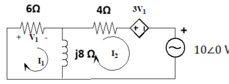
What is the voltage V1 across the 6Ω resistor?
2.64∠−210.74 V
5.00∠−180.00 V
1.20∠−90.00 V
3.50∠−45.00 V
Determine the node voltages V1 and V2 for the circuit with independent sources shown in Fig.4.5.
V1 = 5V, V2 = 2V
V1 = 10V, V2 = 4V
V1 = 3V, V2 = 1V
V1 = 7V, V2 = 3V

Refer to the circuit diagram in Fig. 4.5. What is the KCL equation at node-1 if all currents are assumed to be going away from the node?
10∠35° + I_{-j4} + I_{j10} = 0
10∠35° - I_{-j4} + I_{j10} = 0
10∠35° + I_{-j4} - I_{j10} = 0
10∠35° - I_{-j4} - I_{j10} = 0
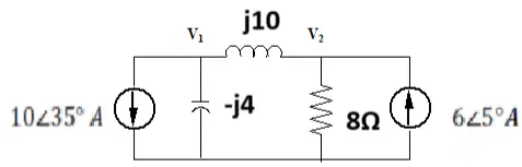
Express the branch current I_{-j4} in terms of node voltages as shown in Step-2.
I_{-j4} = −j4V1−0
I_{-j4} = −j4V2−0
I_{-j4} = −j4V1−V2
I_{-j4} = −j4V2−V1
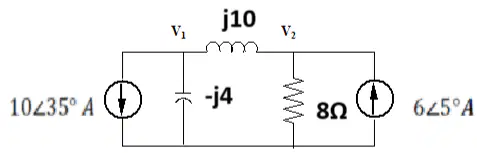
Fill in the blank: The branch current through the inductor j10 is given by I_{j10} = _________.
I_{j10} = j10V1−V2
I_{j10} = j10V2−V1
I_{j10} = j10V1+V2
I_{j10} = 10V1−V2
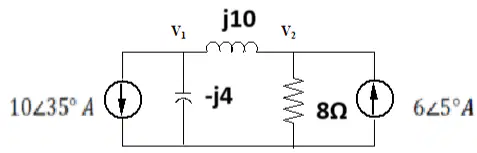
What is the simplified equation obtained after substituting the branch currents into the KCL equation at node-1?
[0.15∠90°]V_1 - [0.1∠-90°]V_2 = -10∠35°
[0.15∠90°]V_1 + [0.1∠-90°]V_2 = -10∠35°
[0.12∠90°]V_1 - [0.15∠-90°]V_2 = -10∠35°
[0.12∠90°]V_1 + [0.15∠-90°]V_2 = -10∠35°
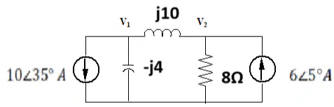
Fill in the blank: The KCL equation at node-2 is _________.
I_{j10} + I_{8\Omega} - 6∠5° = 0
I_{j10} - I_{8\Omega} + 6∠5° = 0
I_{j10} + I_{8\Omega} + 6∠5° = 0
I_{j10} - I_{8\Omega} - 6∠5° = 0
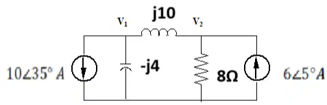
Using Cramer's rule, what is the matrix equation set up to solve for node voltages V_1 and V_2?
\begin{bmatrix} 0.15∠90° & -0.1∠-90° \\ -0.1∠-90° & 0.16∠-38.65° \end{bmatrix} \begin{bmatrix} V_1 \\ V_2 \end{bmatrix} = \begin{bmatrix} -10∠35° \\ 6∠5° \end{bmatrix}
\begin{bmatrix} 0.10∠90° & -0.15∠-90° \\ -0.15∠-90° & 0.16∠-38.65° \end{bmatrix} \begin{bmatrix} V_1 \\ V_2 \end{bmatrix} = \begin{bmatrix} -10∠35° \\ 6∠5° \end{bmatrix}
\begin{bmatrix} 0.15∠90° & -0.1∠-90° \\ -0.1∠-90° & 0.10∠-38.65° \end{bmatrix} \begin{bmatrix} V_1 \\ V_2 \end{bmatrix} = \begin{bmatrix} -10∠35° \\ 6∠5° \end{bmatrix}
\begin{bmatrix} 0.15∠90° & -0.1∠-90° \\ -0.1∠-90° & 0.16∠-90° \end{bmatrix} \begin{bmatrix} V_1 \\ V_2 \end{bmatrix} = \begin{bmatrix} -10∠35° \\ 6∠5° \end{bmatrix}
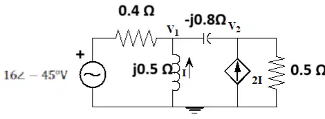
Determine the node voltages V1 and I by nodal analysis in Fig.4.6.
V1 = 5V, I = 2A
V1 = 10V, I = 1A
V1 = 7V, I = 1.5A
V1 = 3V, I = 0.5A
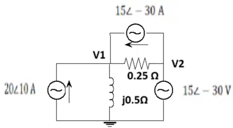
Determine node voltage V1 and current I using super node analysis for the circuit shown in Fig. 4.7 Exercise 6, which consists of independent sources.
V1 = 10V, I = 2A
V1 = 5V, I = 1A
V1 = 8V, I = 1.5A
V1 = 12V, I = 3A
What is resonance in an RLC circuit?
A condition when the frequency or inductance or capacitance is varied at which the reactance of the circuit is zero and hence impedance of the circuit is resistive.
A condition when the resistance is maximum.
A condition when the current is zero.
A condition when the voltage is zero.
Which of the following is NOT an application of the resonance principle in RLC circuits?
Constructing filters with highly frequency selective transfer functions
Selecting desired stations in radio and TV receivers
Increasing the resistance in a circuit
Minimizing switching frequency in power electronics using ZVS and ZCS
Fill in the blank: At resonance, the circuit behaves purely as a ______ network.
resistive
capacitive
inductive
reactive

Refer to the diagram labeled 'Fig.4.8: Series RLC circuit'. Which component is responsible for inductive reactance?
A) R
B) L
C) C
D) V
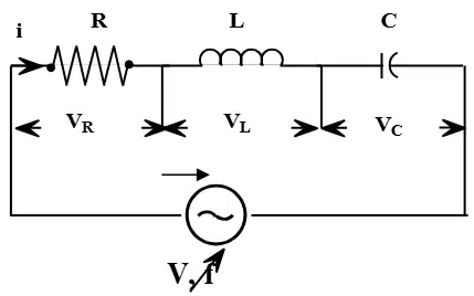
In a series RLC circuit at resonance, the voltage and current are in phase.
True
False
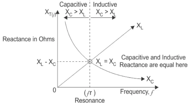
At resonance, what is the relationship between inductive reactance (XL) and capacitive reactance (XC)?
XL > XC
XL < XC
XL = XC
XL + XC = 0
Fill in the blank: The resonant frequency (fr) of a series RLC circuit is given by fr = ________ Hz.
1 / (2π√(LC))
1 / (2πLC)
2π√(LC)
LC / (2π)
What happens to the total impedance of a series RLC circuit at resonance?
It becomes maximum
It becomes minimum and equals R
It equals XL
It equals XC
Fill in the blank: At resonance, the circuit current becomes maximum as impedance reduces, and is given by I = ________.
V / R
V / XL
V / XC
V / Z
At resonance in a series RLC circuit, the voltage across the inductor and capacitor cancels each other, so the voltage across the resistor equals the supply voltage.
True
False
Fill in the blank: Before resonance, ________ reactance dominates in a series RLC circuit.
capacitive
inductive
resistive
conductive
Fill in the blank: After resonance, ________ reactance dominates in a series RLC circuit.
inductive
capacitive
resistive
none
What is the frequency at which resonance in a series RLC circuit occurs?
A) 2πLC1
B) 2πLC1
C) LC1
D) 2L1
At resonance, the total impedance of a series RLC circuit is equal to ________.
Resistance (R)
Inductive reactance (XL)
Capacitive reactance (XC)
Sum of reactances (XL + XC)
The current is maximum at resonant frequency and is given by I = ________.
RV
LV
CV
V⋅R
At resonance, the circuit becomes purely resistive and the phase angle between voltage and current is zero.
True
False
What is the value of the power factor at resonance in a series RLC circuit?
0
0.5
1
0.707
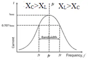
Before resonance ( f < f_r ), which reactance dominates in the circuit?
Inductive reactance
Capacitive reactance
Both are equal
None

After resonance ( f > f_r ), which reactance dominates in the circuit?
Inductive reactance
Capacitive reactance
Both are equal
None
The frequency at which the current is 0.707 times the current at resonance is called ________.
Half power frequency
Resonant frequency
Cut-off frequency
Bandwidth frequency
The bandwidth of an RLC circuit is given by B.W = f2 - f1 = ________.
2πLR
2πRL
R2πL
L2πR
At half power frequencies, the current is given by I = ________.
R/2V
R2V
2RV
RV
Exercise 1: A series RLC circuit has R=1k Ω, an inductor of 100mH and capacitor of 10 μF. An ac supply of 100 V at variable frequency is applied to it. Determine (i) The resonant frequency.
159 Hz
318 Hz
50 Hz
1000 Hz
A series RLC circuit has R=1k Ω, an inductor of 100mH and capacitor of 10 μF. An ac supply of 100 V at variable frequency is applied to it. Determine (ii) The resonant current.
0.1 A
0.01 A
1 A
0.5 A
Exercise 1: A series RLC circuit has R=1k Ω, an inductor of 100mH and capacitor of 10 μF. An ac supply of 100 V at variable frequency is applied to it. Determine (iii) The inductive reactance and capacitive reactance at resonance.
100 Ω (for both)
10 Ω (for both)
1000 Ω (for both)
50 Ω (for both)
A series RLC circuit has R=1k Ω, an inductor of 100mH and capacitor of 10 μF. An ac supply of 100 V at variable frequency is applied to it. Determine (iv) Voltage across resistance, inductance and capacitance at resonance.
100V (resistance), 10V (inductance), 10V (capacitance)
50V (resistance), 100V (inductance), 100V (capacitance)
100V (resistance), 100V (inductance), 100V (capacitance)
10V (resistance), 100V (inductance), 10V (capacitance)
Exercise 1: A series RLC circuit has R=1k Ω, an inductor of 100mH and capacitor of 10 μF. An ac supply of 100 V at variable frequency is applied to it. Determine (v) The bandwidth of the circuit.
159.15
100.00
250.50
500.00
Exercise 1: A series RLC circuit has R=1k Ω, an inductor of 100mH and capacitor of 10 μF. An ac supply of 100 V at variable frequency is applied to it. Determine (vi) The Quality factor Q.
0.1
1.0
10.0
0.01
What is the resonant frequency (ωr) for the given RLC circuit? Fill in the blank: ωr = 1/√(LC) = 1/√(10m × 0.1μ) = ______ radians/sec
31622.77 radians/sec
1000 radians/sec
100000 radians/sec
10 radians/sec
What is the current at resonance (Ir)? Fill in the blank: Ir = Im = V/R = 100/100 = ______ A
1 A
10 A
0.1 A
100 A
What is the voltage across R (VR) at resonance? Fill in the blank: VR = Ir × R = 1 × 100 = ______ V
100 V
10 V
1 V
1000 V
What is the voltage across L (VL) at resonance? Fill in the blank: VL = Ir × XL = 1 × ω × L = 1 × 31622.77 × 10m = ______ V
316.22 V
31.62 V
3.16 V
3162.28 V
What is the voltage across C (VC) at resonance? Fill in the blank: VC = Ir × XC = 1 × 1/(ωr × C) = 1 × 1/(31622.77 × 0.1μ) = ______ V
316.22 V
31.62 V
3.16 V
0.316 V
Calculate R/2L for the given values. Fill in the blank: R/2L = 100/(2 × 10m) = ______
5000
50
5
500
Calculate 1/LC for the given values. Fill in the blank: 1/LC = 1/(10m × 0.1μ) = ______
1×10⁹
1 × 10^6
1×10³
1 × 10^12
What is the value of ω1 for the circuit? Fill in the blank: ω1 = −R/2L+(R/2L)2+1/LC = −5000+50002+1×109 = ______ r/s
27015.62 r/s
15000 r/s
5000 r/s
32000 r/s
What is the value of ω2 for the circuit? Fill in the blank: ω2=+2LR+(2LR)2+LC1 = 5000 + 50002+1×109 = ______ r/s
37015.62 r/s
25000.00 r/s
52000.00 r/s
48000.00 r/s
What is the bandwidth (R/L) for the circuit? Fill in the blank: Bandwidth = R/L = 100/10m = ______ r/s
10,000 r/s
1,000 r/s
100 r/s
10 r/s
What is the difference ω2 - ω1 for the circuit? Fill in the blank: ω2 - ω1 = 37015.62 - 27015.62 = ______ r/s
10,000 r/s
1,000 r/s
27,015.62 r/s
37,015.62 r/s
What is the Q-factor (Q) for the circuit? Fill in the blank: Q = ωr × L / R = 31622.77 × 10m / 100 = ______
3.162
316.23
0.316
31.62
Exercise 3: A series RLC circuit is used to produce a magnification factor of 20 at 100 rad/sec. The source can supply a maximum current of 10 A at 100 V. Find R, L and C. Given: Qr=20, ωr=100 r/s, Im=10 A, V=100 V, R,L,C. (i) What is the value of R? Fill in the blank: Im = Ir = V/R or R = V/Ir = 100/10 = ______ Ω
10 Ω
20 Ω
5 Ω
100 Ω
What is the value of L? Fill in the blank: Qr = ωr × L / R or L = Qr × R / ωr = 20 × 10 / 100 = ______ H
2 H
0.2 H
200 H
20 H
What is the value of C? Fill in the blank: Qr = 1/(ωr × C × R) or C = 1/(Qr × ωr × R) = 1/(20 × 100 × 10) = ______ F
5×10⁻⁵F
5×10⁻⁴F
5×10⁻³F
5×10⁻⁶F
What is parallel resonance in an RLC circuit?
The resonance of a parallel R-L-C circuit is when the current flowing through the circuit is minimum because the admittance of the circuit is minimum.
The resonance of a parallel R-L-C circuit is when the voltage across the circuit is maximum because the impedance is minimum.
The resonance of a parallel R-L-C circuit is when the current flowing through the circuit is maximum because the admittance is maximum.
The resonance of a parallel R-L-C circuit is when the power factor of the circuit is zero.
Which of the following is an application of parallel resonance?
Current amplifier
Frequency selection (e.g., in radio receivers)
Induction heating
All of the above
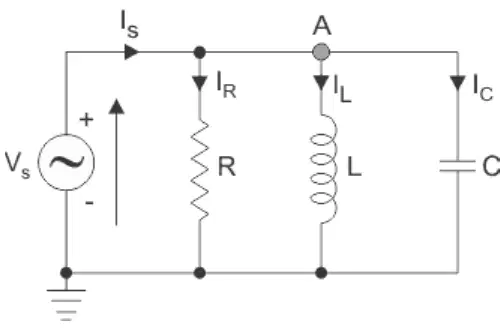
In a parallel RLC circuit, which components are connected in parallel?
Resistor, Inductor, and Capacitor
Resistor and Inductor only
Inductor and Capacitor only
Resistor and Capacitor only
Fill in the blank: The admittance of the circuit is ______ at resonance and equals the conductance G. Therefore the impedance of the circuit is maximum.
minimum
maximum
zero
infinite
What is the formula for the resonant frequency (fr) of a parallel RLC circuit?
fr = 1 / (2π√(LC)) Hz
fr = 2π√(LC) Hz
fr = 1 / (LC) Hz
fr = √(LC) / 2π Hz
At resonance in a parallel RLC circuit, YL = YC.
True
False
What is the expression for the current drawn from the supply at resonance?
VG = V/R
VG = V/L
VG = V/C
VG = V/(R+L+C)
The currents IC and IL are equal and opposite at resonance. What happens to the net current due to IC and IL?
They cancel each other.
The net current doubles.
The net current becomes zero only if frequency increases.
The net current is unaffected.
At resonance, the current is in phase with voltage; the power factor is unity and the circuit acts as a purely resistive circuit.
True
False
Parallel resonance is also known as anti-resonance because the current in the circuit is minimum.
True
False
At resonance, there will be exchange of energy between the inductor and the capacitor. When the inductor is carrying maximum current, what is the voltage across the capacitor?
Zero
Maximum
Equal to supply voltage
Half of supply voltage
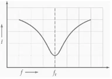
What does the I vs f curve represent in a parallel resonant circuit?
It represents the variation of current with frequency, showing minimum current at resonance frequency.
It represents the variation of voltage with frequency, showing maximum voltage at resonance frequency.
It represents the variation of resistance with frequency, showing minimum resistance at resonance frequency.
It represents the variation of power with frequency, showing maximum power at resonance frequency.
What is the formula for bandwidth (BW) in terms of conductance (G) and capacitance (C)?
BW = G/C
BW = C/G
BW = G*C
BW = G+C
What is the formula for quality factor (Q) in terms of resonant frequency (ωr), conductance (G), and capacitance (C)?
Q = ωrC/G
Q = G/ωrC
Q = ωr/GC
Q = Gωr/C
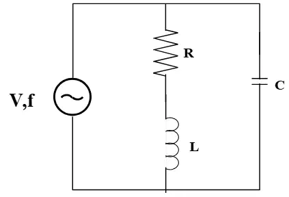
What is the expression for the resonance frequency (fr) of the parallel circuit?
(1/2π)∗(1/LC)−(R2/L2)
fr = (1/2π) * sqrt(LC)
fr = (1/2π) * sqrt(L/C)
fr = (1/2π) * sqrt(C/L)
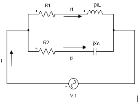
Exercise 4: For a two branch parallel circuit R1=15 Ω, RC=30 Ω, Xc=30 Ω, V=120 V and f=60 c/s. For the condition of resonance, calculate 2 values of L. Use the formula: XL=0.0166(152+XL2) .
XL = 3.75+0.0166XL2 (The value of L can be calculated from this equation; the worksheet does not provide the final numeric values, but this is the derived formula.)
XL = 0.0166(302+XL2)
XL = 0.0166(152−XL2)
XL = 0.0166(152+302)
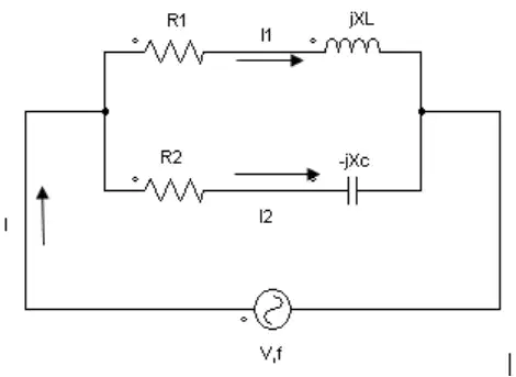
Exercise 4: For a two branch parallel circuit R1=15 Ω, RC=30 Ω, Xc=30 Ω, V=120 V and f=60 c/s. For the condition of resonance, what are the two values of total current?
2.67 A and 4.00 A
1.50 A and 3.00 A
4.00 A and 6.00 A
2.00 A and 3.00 A

A coil of 20 Ω resistance has an inductance of 0.2 H and is connected in parallel with a condenser of 100 μF capacitance. At what frequency will the circuit act as a non-inductive resistance of R ohms?
112.5 Hz
50 Hz
159 Hz
200 Hz
What does 'N' represent in the context of magnetic circuits?
number of turns
magnetic flux
resistance
current
What does 'a' represent in the context of magnetic circuits?
area of cross section in m²
magnetic flux in Weber
length of the magnetic path in meters
permeability of the material
What does 'l' represent in the context of magnetic circuits?
circumferential length in m
magnetic flux in Wb
permeability in H/m
current in A
What does 'Φ' represent in the context of magnetic circuits?
magnetic flux in Wb
magnetic field strength in A/m
magnetomotive force in ampere-turns
reluctance in 1/H
What does 'I' represent in the context of magnetic circuits?
current in A
magnetic flux in Wb
magnetomotive force in At
reluctance in H^-1
In a magnetic circuit, what is the opposition to magnetic flux called?
reluctance
conductance
inductance
resistance
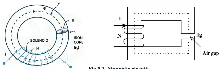
The function of the air gap in a magnetic circuit is:
to increase the reluctance and control the flux in the circuit
to decrease the resistance of the circuit
to enhance the conductivity of the magnetic material
to eliminate eddy currents completely
What is the primary material within the magnetic circuit, often made of iron or steel that provides a path for the magnetic flux?
Plastic
Iron
Wood
Glass
Which of the following is NOT an example of a material used as a magnetic core?
Air
Iron
Ferrite
Copper
A non-magnetic space within the magnetic circuit, often introduced to control the magnetic field or create a specific magnetic effect, is called _______.
Air Gap
Flux Linkage
Core Saturation
Magnetic Reluctance
What is a magnetic field?
A region around a magnet where magnetic field lines are used to visualize the field
A type of electric current
A type of resistance
A type of mechanical force
Magnetic field strength is often denoted by ____ and its SI unit is _______.
H, ampere per meter (A/m)
B, tesla (T)
M, weber (Wb)
E, volt per meter (V/m)
The driving force that creates magnetic flux, analogous to electromotive force (EMF) in an electrical circuit, is called ________.
Magnetomotive Force (MMF)
Electrostatic Force (ESF)
Magnetic Susceptibility
Inductive Reactance
The unit of Magnetomotive Force (MMF) is:
Weber
Ampere-turns (AT)
Tesla
Henry

