
 Worksheets
Key Concept 7 – Electrical Circuits (Worksheet Questions)
Total questions: 126
Worksheet time: 1hrs 3mins
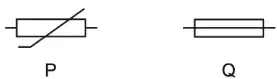
P and Q are the circuit symbols for two electrical components. Which components are represented by P and by Q?
thermistor fuse
thermistor relay
variable resistor fuse
variable resistor relay
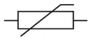
A circuit contains the component shown by the following symbol. Which change would the component detect? A change in ___.
light level
potential difference
radioactivity
temperature
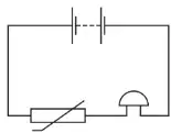
A student sets up this circuit. What is the purpose of the circuit?
to allow a lamp to be made dimmer or brighter as required
to amplify the sound of a voice
to light a lamp in the dark
to sound a bell when the temperature rises
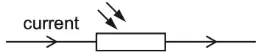
A source of constant electromotive force (e.m.f) is connected across a light-dependent resistor (LDR). There is an electric current in the LDR. The brightness of the light falling on the LDR is reduced. Which row shows what happens to the resistance of the LDR and what happens to the current?
resistance decreases, current decreases
resistance decreases, current increases
resistance increases, current decreases
resistance increases, current increases
What is the function of a relay?
to allow a current in one circuit to operate a switch in another circuit
to prevent an electric shock by earthing a metal case
to protect a circuit by melting if the current becomes too large
to transform a d.c. voltage to a different value
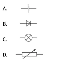
Which electrical symbol represents a diode?
A
B
C
D
A diode is used as a rectifier. What is the purpose of a rectifier?
to allow current to pass in either direction
to change alternating current into direct current
to switch off the circuit in case of a large current
to provide an efficient source of light
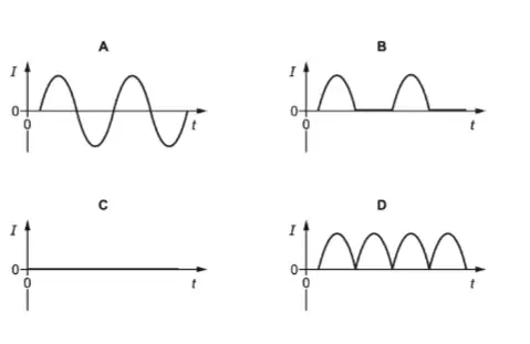
The circuit diagram shows a circuit with an a.c. supply, a diode and a resistor. Which diagram shows how the current I in the resistor varies with time t?
A
B
C
D
Two resistors are connected in series with a power supply. Which statement about the circuit is correct?
The current from the supply is greater than the current in each resistor.
The current from the supply is equal to the current in each resistor.
The current from the supply is less than the current in each resistor.
The current from the supply is the sum of the currents in each resistor.
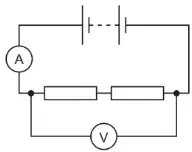
A student uses the circuit shown to determine the resistance of two identical resistors. The voltmeter reading is 2.2 V and the ammeter reading is 0.25 A. What is the resistance of each resistor?
0.275 Ω
0.55 Ω
4.4 Ω
8.8 Ω
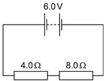
The circuit diagram shows a 4.0 Ω resistor and an 8.0 Ω resistor connected to a 6.0 V battery. What is the current in the battery?
0.50 A
0.75 A
1.5 A
2.0 A
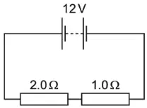
The circuit shows a 2.0 Ω resistor and a 1.0 Ω resistor connected to a 12 V battery. What is the current in the 2.0 Ω resistor?
4.0 A
6.0 A
24 A
36 A
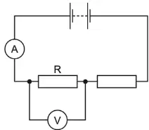
The circuit shows a 24 V battery connected to two resistors in series. The reading on the ammeter is 2.0 A and the reading on the voltmeter is 8.0 V. What is the resistance of resistor R?
0.25 Ω
4.0 Ω
10 Ω
16 Ω
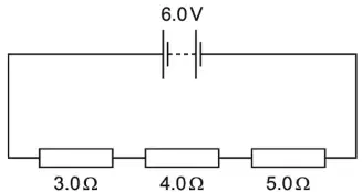
The circuit diagram shows three resistors connected in series across a 6.0 V supply. What is the potential difference (p.d.) across the 4.0 Ω resistor?
0.67 V
1.5 V
2.0 V
6.0 V
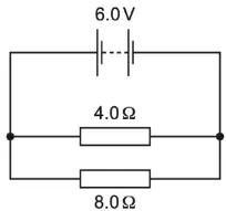
The circuit diagram shows a 4.0 Ω resistor and an 8.0 Ω resistor connected to a 6.0 V battery. What is the potential difference (p.d.) across the 4.0 Ω resistor?
0.5 V
2.0 V
4.0 V
6.0 V
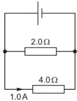
A cell is connected to a parallel combination of a 2.0 Ω resistor and a 4.0 Ω resistor. The current in the 4.0 Ω resistor is 1.0 A. What is the current in the cell?
1.0 A
1.5 A
2.0 A
3.0 A
Resistors of 1.0 Ω, 2.0 Ω and 3.0 Ω are connected in parallel with a cell. Which statement is correct?
The current in each resistor is different but the potential difference (p.d.) across each resistor is the same.
The current in each resistor is the same but the potential difference across each resistor is different.
The potential difference across the 3.0 Ω is greater than the potential difference across the 1.0 Ω resistor.
The sum of the potential differences across each resistor is equal to the electromotive force (e.m.f.) of the cell.
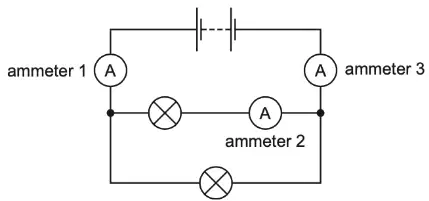
The diagram shows a circuit containing two identical lamps and three ammeters. The current in ammeter 1 is 0.30 A. Which row gives possible values for the currents in ammeters 2 and 3?
0.15 A, 0.00 A
0.15 A, 0.30 A
0.30 A, 0.00 A
0.30 A, 0.30 A
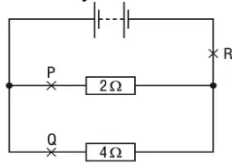
A circuit contains two resistors connected in parallel with a battery. Which of the following statements about the currents at P, Q and R is true?
The current at P is the greatest.
The current at Q is the greatest.
The current at R is the greatest.
The current is the same at points P, Q and R.
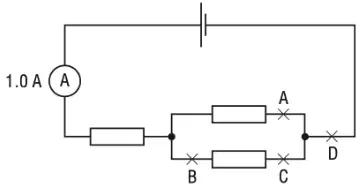
The reading on the ammeter in the circuit is 1.0 A. A second ammeter is connected in the circuit. It also reads 1.0 A. At which labelled point is it connected?
A
B
C
D
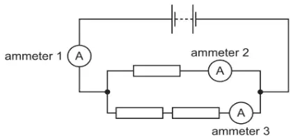
The diagram shows three identical resistors, three ammeters and a battery, connected in a circuit. What is the order of the magnitudes of the readings on the ammeters from smallest to largest?
A 1, A 2, A 3
A 1, A 3, A 2
A 2, A 3, A 1
A 3, A 2, A 1
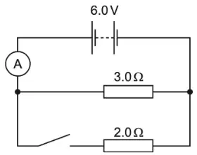
The diagram shows a circuit with a 3.0 Ω resistor and a 2.0 Ω resistor connected in parallel. The switch is open, and the ammeter reads 2.0 A. The switch is now closed and the ammeter reads the total current in both resistors. What is the ammeter reading with the switch closed?
1.2 A
3.0 A
4.0 A
5.0 A
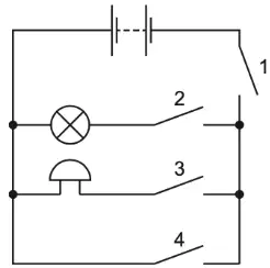
A student connects the circuit shown. Which switches must be closed for both the bell to ring and the lamp to light?
1 and 4 only
2 and 3 only
1, 2 and 3 only
1, 2, 3 and 4
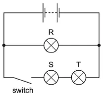
The diagram shows an electric circuit. When the switch is open, which lamp or lamps are not lit?
R only
S only
R, S and T
S and T only
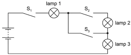
The diagram shows a circuit containing three lamps and three switches S1 , S2 and S3 . Lamp 1 and lamp 3 are lit, but lamp 2 is not lit. Which switch or switches is/are closed?
S1 only
S1 and S2
S1 and S3
S2 and S3
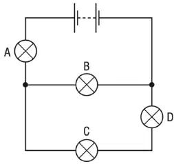
The circuit shows a battery and four lamps labelled A, B, C and D. All the lamps are lit. One lamp fails and all the lamps go out. Which lamp failed?
A
B
C
D
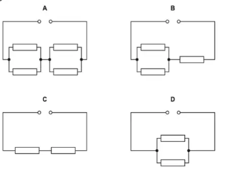
In the circuits shown, each resistor has a resistance of 1.0 Ω. Which circuit has the greatest resistance?
A
B
C
D
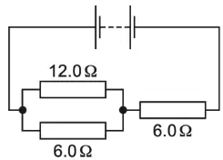
A 12.0 Ω resistor and a 6.0 Ω resistor are connected in parallel. Another 6.0 Ω resistor is then connected in series with the parallel combination. What is the combined resistance of all three resistors?
8.0 Ω
10 Ω
15 Ω
24 Ω
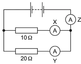
The circuit shown contains three ammeters X, Y and Z. Which ammeter has the largest reading?
X
Y
Z
They all have the same reading
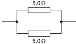
Two 5.0 Ω resistors are connected as shown in the diagram. What is the total resistance of this combination?
less than 5.0 Ω
5.0 Ω
more than 5.0 Ω but less than 10.0 Ω
10.0 Ω
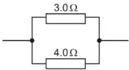
A 3.0 Ω resistor is connected in parallel with a 4.0 Ω resistor. What is the resistance of this combination?
0.14 Ω
0.58 Ω
1.7 Ω
7.0 Ω
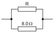
A resistor R is connected in parallel with an 8.0 Ω resistor. The resistance of this combination is 4.0 Ω. What is the resistance of resistor R?
0.50 Ω
2.0 Ω
4.0 Ω
8.0 Ω
Lamps in a circuit are connected in parallel. What is the advantage of this?
If one lamp breaks, the others remain lit.
Less current is taken from the power supply.
The lamps use less power than if they were connected in series.
The potential difference across each lamp is less than that of the power supply.
Which statement is not correct for lamps connected in parallel?
They can be switched on and off separately.
They will remain bright if another lamp is connected in parallel.
They share the supply voltage equally between them.
They still operate if one lamp is removed.
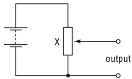
The circuit shown is a potential divider. What is component X?
a light-dependent resistor
a relay
a thermistor
a variable resistor

A student connects a variable potential divider (potentiometer) circuit. As the sliding terminal T is moved from R to S, what happens to the reading on the voltmeter?
It decreases from 12 V to 0 V.
It increases from 0 V to 12 V.
It remains at 0 V.
It remains at 12 V.
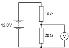
The diagram shows a 10 Ω resistor and a 20 Ω resistor connected in a potential divider circuit. What is the reading on the voltmeter?
4.0 V
6.0 V
8.0 V
12.0 V

An engineer uses the potential divider shown in the diagram. He needs the output voltage to be one tenth (1/10) of the input voltage. Which pair of values could he use for the two resistors X and Y?
X 1.0 kΩ, Y 9.0 kΩ
X 1.0 kΩ, Y 10.0 kΩ
X 9.0 kΩ, Y 1.0 kΩ
X 10.0 kΩ, Y 1.0 kΩ
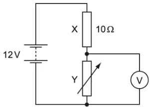
A circuit is connected for use as a potential divider. The resistance of resistor X is 10 Ω. When the resistance of the variable resistor Y is 20 Ω, what is the reading on the voltmeter?
4.0 V
6.0 V
8.0 V
12 V
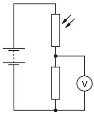
The diagram shows an electric circuit. The light falling on the light-dependent resistor (LDR) increases in brightness. What happens to the resistance of the LDR, the current in the fixed resistor and the reading on the voltmeter?
resistance of LDR decreases; current in fixed resistor increases; reading on voltmeter decreases
resistance of LDR decreases; current in fixed resistor increases; reading on voltmeter increases
resistance of LDR increases; current in fixed resistor decreases; reading on voltmeter decreases
resistance of LDR increases; current in fixed resistor decreases; reading on voltmeter increases
Where must a fuse be connected in a mains electric circuit?
the earth wire only
the live wire only
the neutral wire only
the live wire and the earth wire
Which electrical component is connected in series with an electric circuit to protect it from damage by a very large current?
earth wire
fuse
relay
thermistor
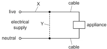
Either a fuse or a circuit-breaker can be used to protect electrical cables from large currents that could cause overheating. When a fuse is used, where should it be connected, and when a circuit-breaker is used, where should it be connected?
position of the fuse: X; position of the circuit breaker: X
position of the fuse: X; position of the circuit breaker: Y
position of the fuse: Y; position of the circuit breaker: X
position of the fuse: Y; position of the circuit breaker: Y
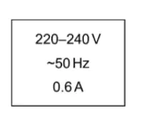
The information on the back of a television is shown. Which fuse provides the best protection for the circuit?
0.5 A
1.0 A
5.0 A
13 A
The current in a lamp connected on its own to the mains supply is 0.60 A. A table decoration has three of these lamps connected in parallel. Which rating of fuse is suitable to protect this circuit?
0.2 A
0.6 A
1.0 A
5.0 A
Two electrical appliances are connected to the mains supply. The cable connected to one appliance includes an earth wire. The cable connected to the second appliance does not need an earth wire. What is a reason for this difference?
One appliance has a metal case, but the other appliance does not.
One appliance is fitted with a fuse, but the other appliance is not.
One appliance is fitted with a switch, but the other appliance is not.
One appliance needs more current than the other appliance.
An electric kettle has a metal casing. The cable for the kettle contains a wire that is connected to the earth pin of the plug. Which danger does this guard against?
the cable to the kettle becoming too hot
the casing of the kettle becoming live
the casing of the kettle becoming wet on the outside
the casing of the kettle overheating
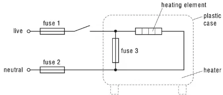
The diagram shows the connections to an electric heater. Three fuses have been added to the circuit. Which of the fuses are correctly placed?
fuse 1, fuse 2 and fuse 3
fuse 1 and fuse 2 only
fuse 1 only
fuse 2 only
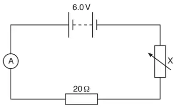
The figure shows a circuit that contains a battery of electromotive force 6.0V , an ammeter, a 20Ω resistor and component X. State the name of component X.
Variable resistor (rheostat)
Voltmeter
Switch
Cell
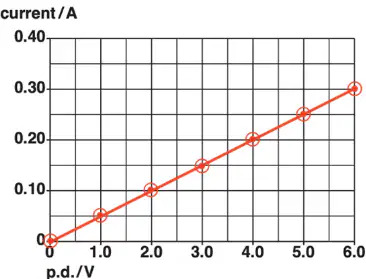
The p.d. across the 20Ω resistor is varied from 0 to 6.0V . For each value of p.d., a corresponding current is measured. Which description best matches the line that should be drawn on the current–p.d. graph for the 20Ω resistor?
A straight line through the origin showing current directly proportional to p.d.
A horizontal line showing current independent of p.d.
A curve that decreases as p.d. increases (inverse relationship)
An exponential increase starting above the origin
A second resistor is connected into the circuit in parallel with the 20Ω resistor. State how the combined resistance of the two resistors in parallel compares with the resistance of each resistor on its own.
It is less than the resistance of the smaller resistor.
It equals the resistance of the larger resistor.
It is between the smaller and larger resistances.
It is greater than the resistance of the larger resistor.
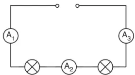
Fig. 9.1 shows a circuit with two lamps and three ammeters connected in series to a power supply. The current shown on ammeter A1 is 0.6A . What current would be shown on ammeter A2 ?
0.6A
0.3A
1.2A
0A
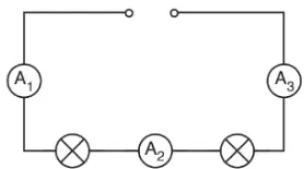
Fig. 9.1 shows a circuit with two lamps and three ammeters connected in series to a power supply. The current shown on ammeter A1 is 0.6A . What current would be shown on ammeter A3 ?
0.6A
0.3A
1.2A
0A
The resistance of each lamp is 20Ω . Determine the combined resistance of the two lamps when connected in series.
40Ω
20Ω
10Ω
60Ω
The circuit is changed. The two lamps are connected in parallel. Compare the current from the power supply with the current in each lamp.
The current from the source is higher than the current in each lamp.
The current from the source is equal to the current in each lamp.
The current from the source is lower than the current in each lamp.
The current from the source is zero.
The circuit with two lamps is changed to parallel. Compare the resistance of one lamp in this circuit with the combined resistance of the two lamps connected in parallel.
Combined resistance in parallel is less than the resistance of one lamp.
Combined resistance in parallel equals the resistance of one lamp.
Combined resistance in parallel is greater than the resistance of one lamp.
Combined resistance in parallel is twice the resistance of one lamp.
A different series circuit contains a fixed resistor of 140Ω . An ammeter shows a current of 0.30A . Calculate the potential difference across the resistor. State the unit.
42V
0.42V
4.2V
140V
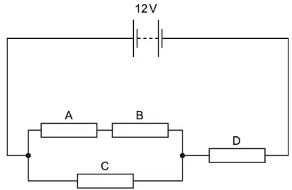
Fig. 9.1 shows a 12V battery connected in a circuit containing resistors A, B, C and D. Each resistor has a resistance of 6.0Ω . Calculate the combined resistance of resistors A and B.
12Ω
6.0Ω
4.0Ω
18Ω
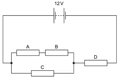
Using Fig. 9.1 with A, B, C each 6.0Ω , calculate the combined resistance of resistors A, B and C.
4.0Ω
12Ω
6.0Ω
10Ω
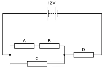
Using Fig. 9.1 with A, B, C and D each 6.0Ω , calculate the combined resistance of resistors A, B, C and D.
10Ω
4.0Ω
12Ω
6.0Ω
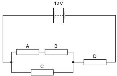
For the circuit in Fig. 9.1 with a 12V battery and combined resistance 10Ω , calculate the current in the battery.
1.2A
0.12A
0.60A
2.0A
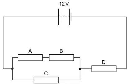
For the circuit in Fig. 9.1, calculate the energy transferred from the battery to the circuit in 50s when V=12V and I=1.2A .
720J
60J
120J
7.2kJ
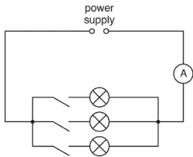
Fig. 7.1 shows three identical lamps and an ammeter connected to a power supply. The switches are closed. Each lamp is rated at 60W and operates at its normal working voltage of 110V . Calculate the current in each lamp.
0.55A
1.6A
0.60A
0.50A
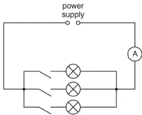
With the three identical lamps each drawing the same current, calculate the current in the ammeter in Fig. 7.1.
1.6A
0.55A
3.3A
0.60A
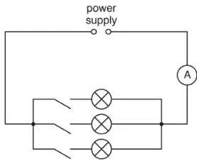
In the setup of Fig. 7.1, state the voltage of the power supply when the lamps operate at their normal working voltage.
110V
60V
12V
240V
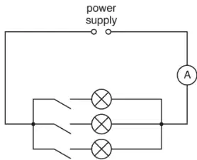
Calculate the resistance of the filament of one lamp in Fig. 7.1 when working normally.
200Ω
60Ω
0.55Ω
110Ω
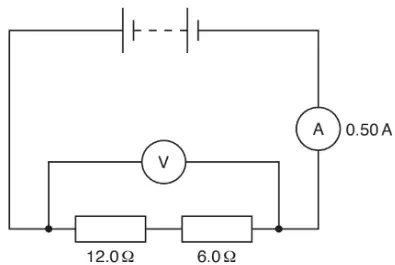
Fig. 9.1 shows a simple circuit with an ammeter reading 0.50A and two resistors of 12.0Ω and 6.0Ω in series. Calculate the combined resistance of the two resistors.
18Ω
12Ω
6.0Ω
24Ω
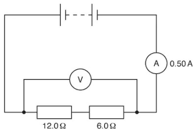
For the circuit in Fig. 9.1 with I=0.50A and combined resistance 18Ω , calculate the potential difference reading that would be shown on the voltmeter.
9.0V
0.50V
18V
3.0V
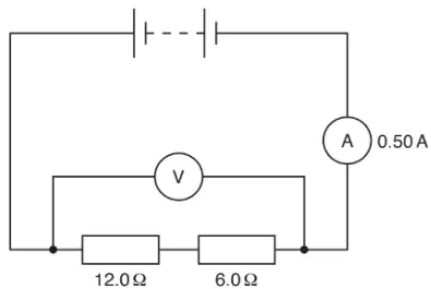
The circuit in Fig. 9.1 is changed so the two resistors are connected in parallel. Explain what happens, if anything, to the current reading on the ammeter.
It increases because the effective circuit resistance decreases.
It decreases because the effective circuit resistance increases.
It stays the same because total resistance is unchanged.
It drops to zero because the voltmeter is removed.
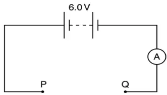
In the circuit shown in Fig. 9.1, resistors can be connected between terminals P and Q. The e.m.f. of the battery is 6.0V . Calculate the current shown by the ammeter when a 12.0Ω resistor and a 4.0Ω resistor are connected in series between P and Q.
0.38A
2.0A
0.14A
1.5A
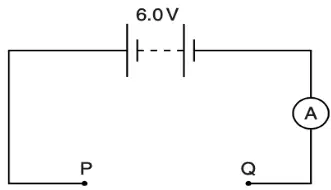
In the Fig. 9.1 circuit with battery 6.0V , calculate the current when 12.0Ω and 4.0Ω resistors are connected in parallel between P and Q.
2.0A
0.38A
0.75A
0.14A
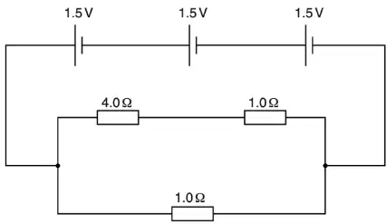
Fig. 8.1 shows three cells each with e.m.f. 1.5V connected in series. Calculate the combined e.m.f. of the cells.
4.5V
3.0V
1.5V
6.0V
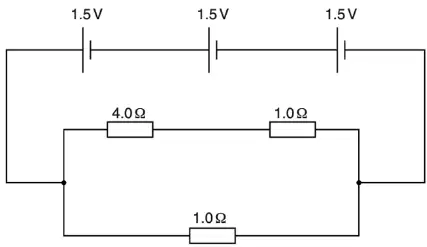
Fig. 8.1 shows three resistors 4.0Ω , 1.0Ω , and 1.0Ω arranged with the 4.0Ω and 1.0Ω (top) in series and in parallel with the bottom 1.0Ω . Calculate the combined resistance of the three resistors.
0.83Ω
5.0Ω
2.0Ω
1.0Ω
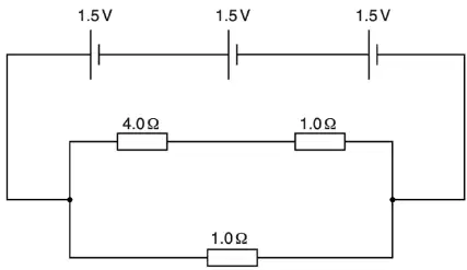
Calculate the current in the 4.0Ω resistor in Fig. 8.1 when the combined e.m.f. is 4.5V .
0.90A
4.5A
0.20A
0.45A
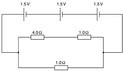
Calculate the combined e.m.f. of the cells in Fig. 8.1 if one cell is reversed.
1.5V
0V
3.0V
4.5V
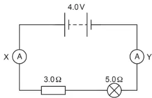
Fig. 10.1 shows a lamp and a resistor connected in a circuit with a 4.0V supply and ammeters X and Y. Determine the combined resistance of the 3.0Ω resistor and the 5.0Ω lamp when connected in series.
8.0Ω
3.0Ω
5.0Ω
4.0Ω
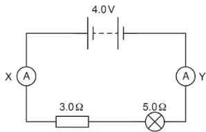
In Fig. 10.1, the reading on ammeter X is 0.50A . State the reading on ammeter Y.
0.50A
0.25A
1.0A
0A
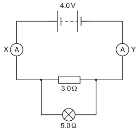
Fig. 10.2 shows the 3.0Ω resistor and 5.0Ω lamp connected in parallel to a 4.0V supply with ammeters X and Y. What is the combined resistance in parallel?
1.9Ω
3.0Ω
5.0Ω
8.0Ω
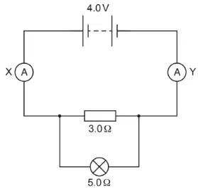
In Fig. 10.2, state and explain the effect of changing from series to parallel on the current in ammeter X.
It increases because the circuit resistance decreases.
It decreases because the circuit resistance increases.
It stays the same because resistance is unchanged.
It becomes zero because parallel branches cancel current.
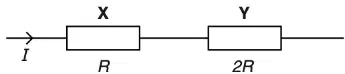
Fig. 8.1 shows two resistors X and Y in series. Complete the table using only the symbols I and R . What is the current through each resistor?
I
2I
I/2
0
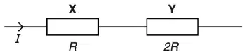
For the series circuit with resistors X ( R ) and Y ( 2R ), what is the potential difference across resistor X expressed using I and R ?
IR
2IR
I2R
R/I
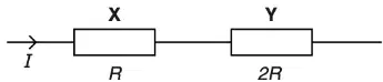
For the series circuit with resistors X ( R ) and Y ( 2R ), what is the potential difference across resistor Y expressed using I and R ?
2IR
IR
I2R
R/I
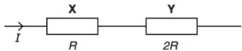
For the series circuit with resistors X ( R ) and Y ( 2R ), which expression gives the power dissipated in resistor Y?
2I2R
I2R
IR
2IR
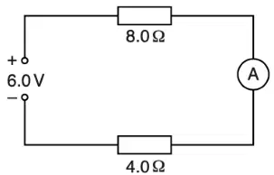
Fig. 8.1 shows a circuit with a 6.0 V power supply and two series resistors of 8.0 Ω and 4.0 Ω with an ammeter. Calculate the combined resistance of the two resistors.
8 Ω
12 Ω
4 Ω
2 Ω
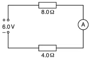
For the circuit in Fig. 8.1 with a 6.0 V supply and series resistors of 8.0 Ω and 4.0 Ω, calculate the current indicated by the ammeter. Include the unit.
0.25 A
0.50 A
1.5 A
2.0 A
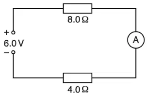
In Fig. 8.1, the 8.0 Ω resistor is replaced by another resistor with a larger resistance. Without further calculation, state the effect on the ammeter reading.
Increases
Decreases
Remains the same
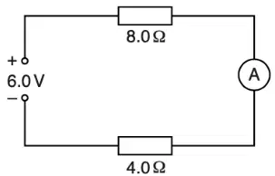
In Fig. 8.1, the 8.0 Ω resistor is replaced by a larger resistance. Without further calculation, state the effect on the potential difference across the 4.0 Ω resistor.
Increases
Decreases
Remains the same
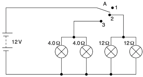
A circuit operates two headlights and two sidelights of a car. Two lamps have resistances of 4.0 Ω when lit and two lamps have resistances of 12 Ω when lit. Switch A can be connected to positions 1, 2 or 3. State what happens when switch A is connected to position 1.
All lamps off
Only 4.0 Ω lamps on
Only 12 Ω lamps on
All lamps on
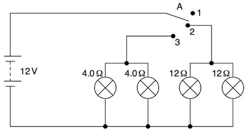
In the same circuit with switch A, state what happens when switch A is connected to position 2.
All lamps off
Only 4.0 Ω lamps on
Only 12 Ω lamps on
All lamps on
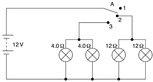
In the same circuit with switch A, state what happens when switch A is connected to position 3.
All lamps off
Only 4.0 Ω lamps on
Only 12 Ω lamps on
All lamps on

State the potential difference across each lamp when lit in the car-lamp circuit.
6 V
9 V
12 V
18 V
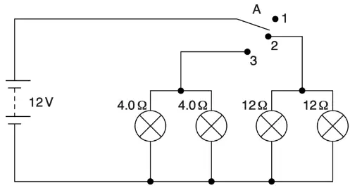
Calculate the current in each 12 Ω lamp when lit in the car-lamp circuit.
0.25 A
0.50 A
1.0 A
2.0 A
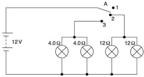
Which type of lamp, 4.0 Ω or 12 Ω, has the higher power when lit by 12 V?
4.0 Ω lamp
12 Ω lamp
Both have the same power
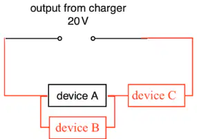
Three devices A, B and C are connected together and then to a 20 V charger. The potential differences are measured as: across A is 14 V, across B it is 14 V, and across C it is 6 V. Which arrangement of A, B and C is consistent with these measurements?
A and B in parallel, combined in series with C
A, B and C all in series
A, B and C all in parallel
A in series with B; both parallel with C
Two devices, D and E, have resistances of 20 Ω and 30 Ω. Calculate the total resistance when D and E are connected in parallel.
8 Ω
12 Ω
20 Ω
25 Ω
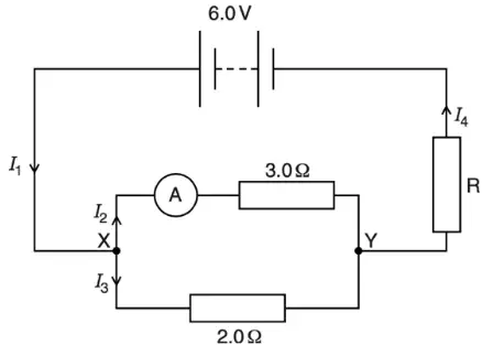
For the circuit shown, state the relationship between the currents I1, I2 and I3.
I1 = I2 + I3
I1 = I2 − I3
I1 = I3 − I2
I1 = I2 = I3
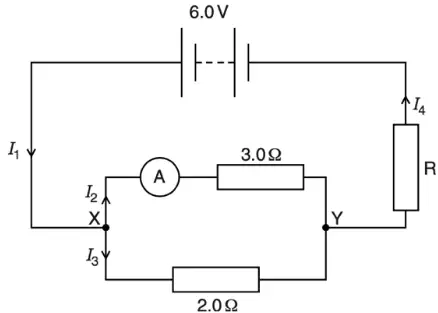
For the same circuit, state the relationship between the currents I1 and I4.
I1 = I4
I1 > I4
I1 < I4
I1 + I4 = 0
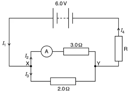
The ammeter reads 0.80 A and has zero resistance. Calculate the potential difference between X and Y.
1.2 V
2.4 V
3.6 V
6.0 V
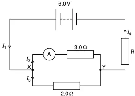
Using the potential difference between X and Y, calculate the current I3 through the 2.0 Ω resistor.
0.40 A
0.80 A
1.2 A
1.6 A
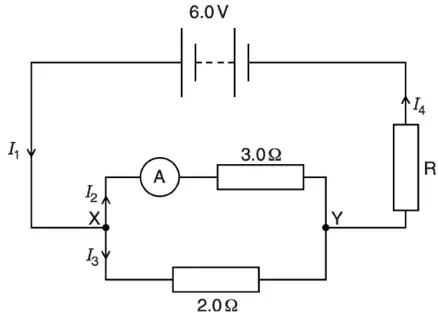
Calculate the resistance of R in the circuit, assuming the ammeter has zero resistance.
0.6 Ω
1.2 Ω
1.8 Ω
3.6 Ω
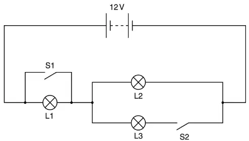
In the circuit with a 12 V car battery and switches S1 and S2 controlling lamps L1, L2 and L3, when S1 and S2 are both open, which two lamps are in series?
L1 and L2
L1 and L3
L2 and L3
None are in series
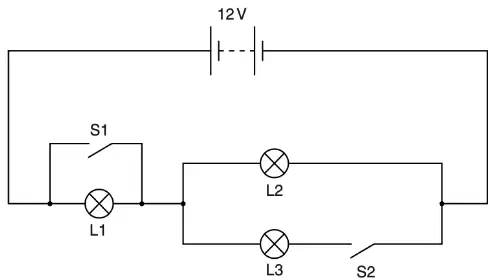
In the same circuit, when S1 and S2 are both closed, which two lamps are in parallel?
L1 and L2
L1 and L3
L2 and L3
None are in parallel
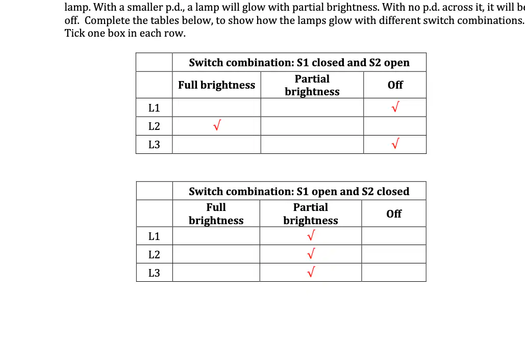
Switch combination: S1 closed and S2 open. How does lamp L1 glow? Tick one level of brightness.
Full brightness
Partial brightness
Off
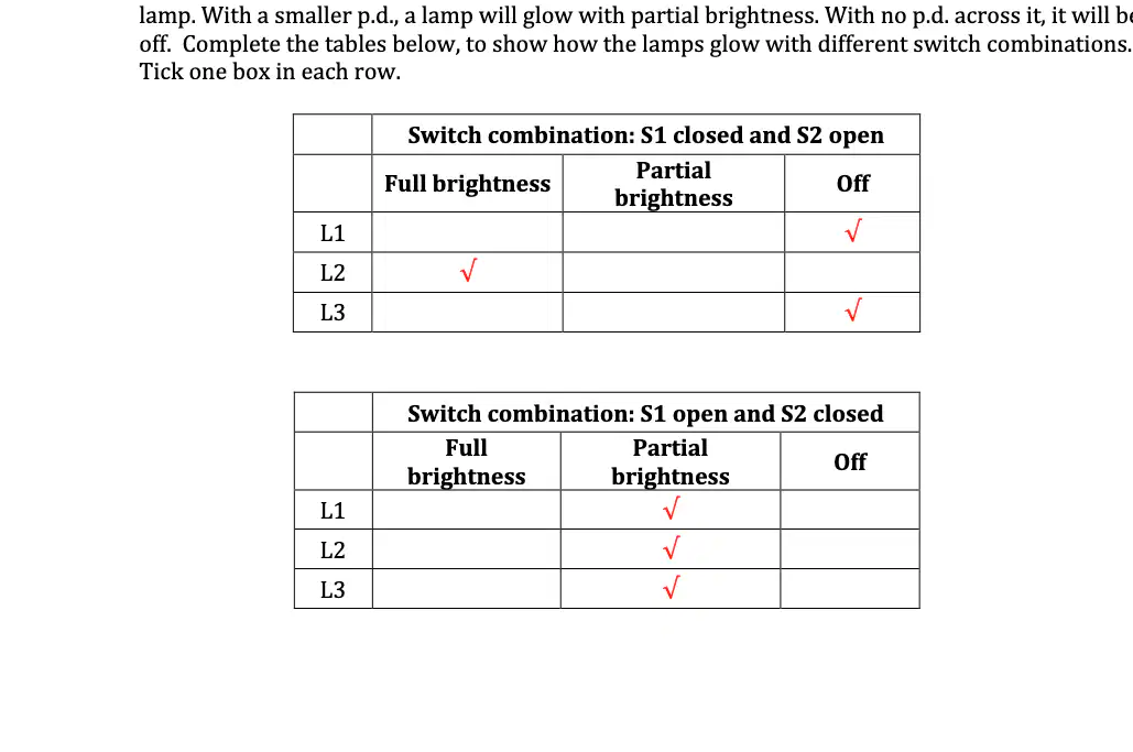
Switch combination: S1 closed and S2 open. How does lamp L2 glow? Tick one level of brightness.
Full brightness
Partial brightness
Off
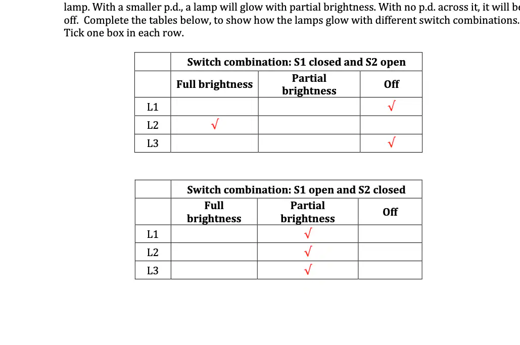
Switch combination: S1 closed and S2 open. How does lamp L3 glow? Tick one level of brightness.
Full brightness
Partial brightness
Off
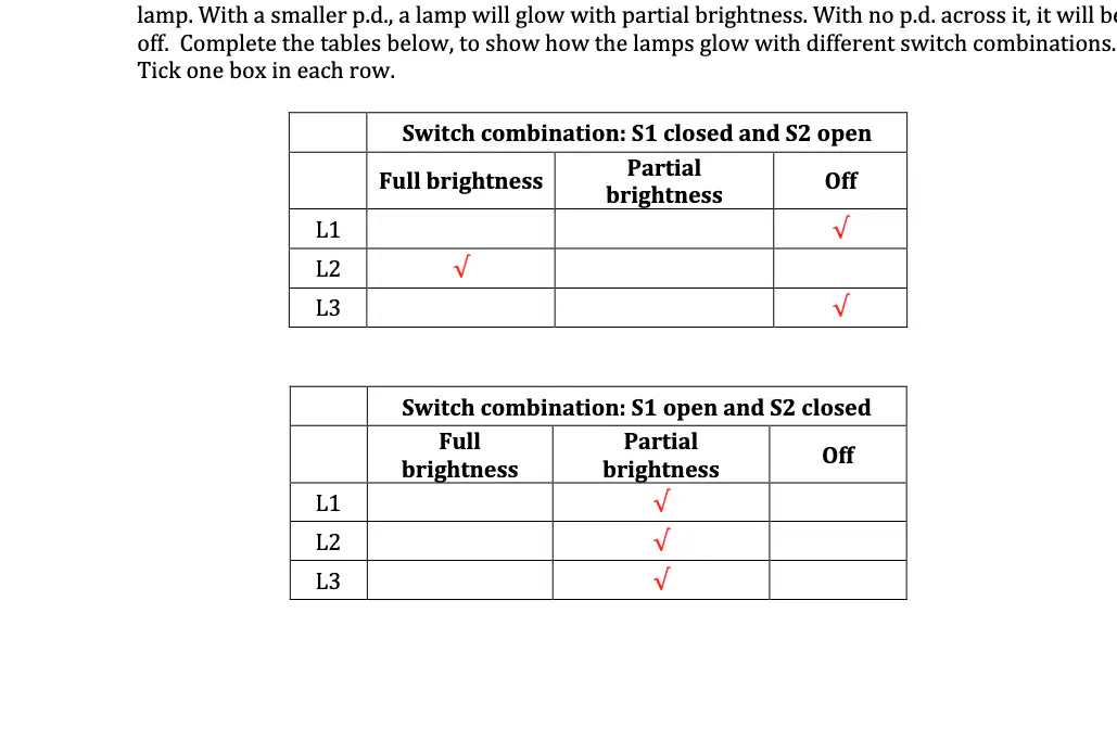
Switch combination: S1 open and S2 closed. How does lamp L1 glow? Tick one level of brightness.
Full brightness
Partial brightness
Off
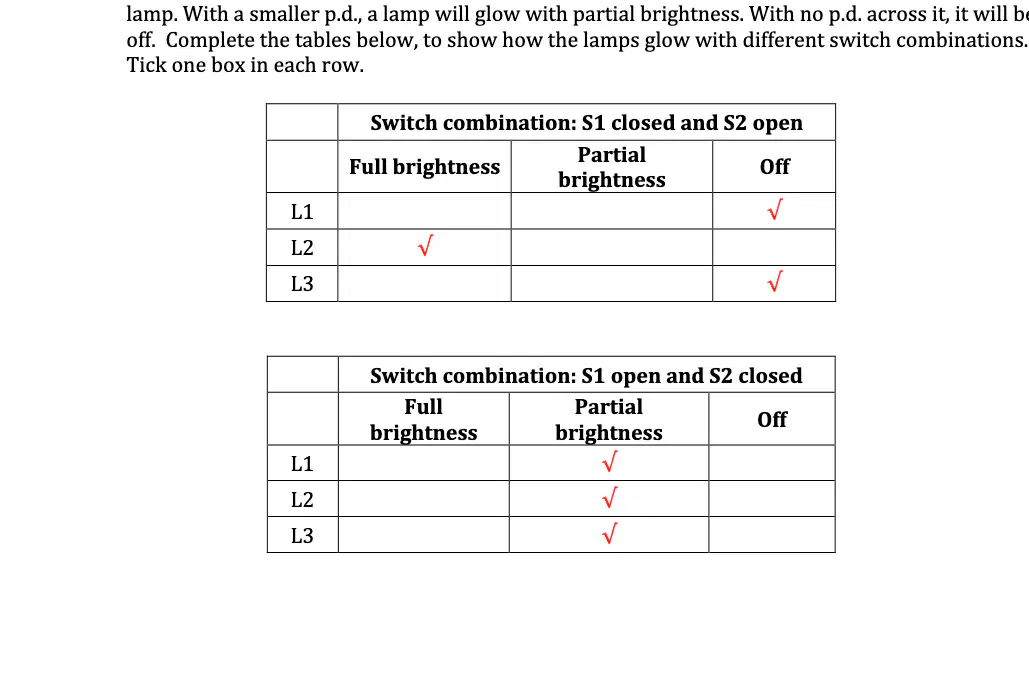
Switch combination: S1 open and S2 closed. How does lamp L2 glow? Tick one level of brightness.
Full brightness
Partial brightness
Off
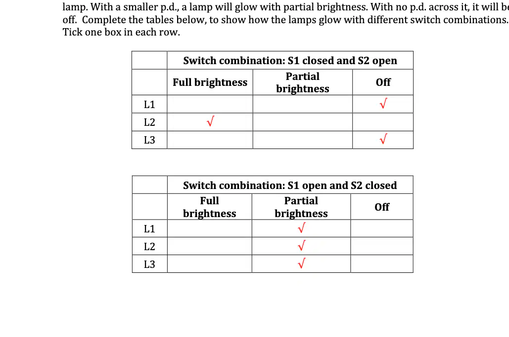
Switch combination: S1 open and S2 closed. How does lamp L3 glow? Tick one level of brightness.
Full brightness
Partial brightness
Off
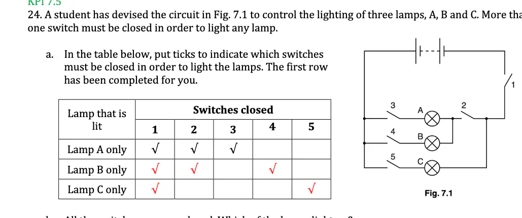
A circuit controls three lamps A, B and C with five switches 1–5. More than one switch must be closed to light any lamp. All the switches are now closed. Which of the lamps light up?
Only A
Only B
Only C
All of them
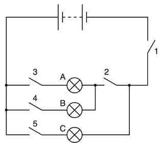
In the same circuit of Fig. 7.1, which one switch must be open to ensure that none of the lamps light up?
Switch 1
Switch 2
Switch 3
Switch 4
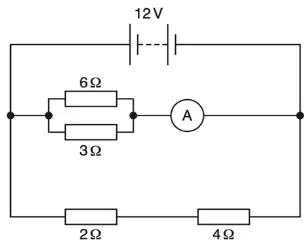
Fig. 7.1 shows a circuit containing a 12 V power supply, some resistors and an ammeter of negligible resistance. Determine the potential difference across the 2 Ω resistor.
2 V
4 V
6 V
12 V
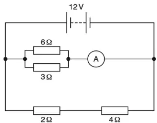
For the circuit in Fig. 7.1, state the potential difference across the 3 Ω resistor.
2 V
4 V
6 V
12 V
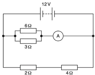
Calculate the effective resistance of the 2 Ω and 4 Ω resistors when connected in series.
4 Ω
6 Ω
8 Ω
10 Ω
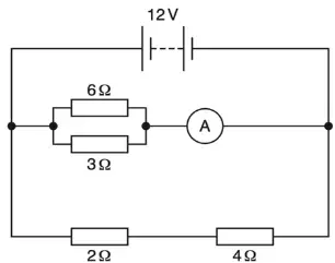
Calculate the effective resistance of the 3 Ω and 6 Ω resistors when connected in parallel.
1.5 Ω
2.0 Ω
3.0 Ω
6.0 Ω
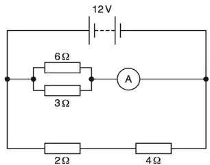
Calculate the reading on the ammeter in Fig. 7.1.
2 A
4 A
6 A
8 A
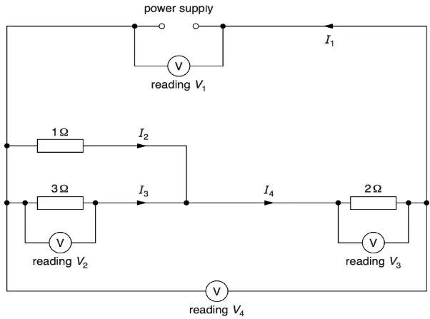
Fig. 8.1 shows a circuit with three resistors, a power supply, and four voltmeters. Calculate the combined resistance of the three resistors.
1.75 Ω
2.00 Ω
2.50 Ω
2.75 Ω
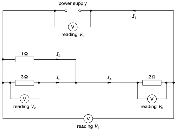
Write down two relationships for the currents in the circuit of Fig. 8.1. Select all that are correct.
I1 = I4
I2 + I3 = I1
I2 = I3
I1 = I2 − I3
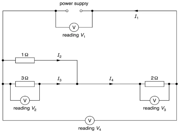
Write down two relationships for the voltmeter readings in the circuit of Fig. 8.1. Select all that are correct.
V1 = V4
V2 + V3 = V1
V2 = V3
V3 > V2
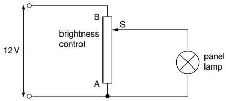
The circuit for adjusting the brightness of the lamp in the display panel of a car is shown in Fig. 10.1. The brightness control is uniformly wound with resistance wire and has a sliding contact S. State the name of the component used as the brightness control.
Fixed resistor
Variable resistor (rheostat/potentiometer)
Diode
Battery
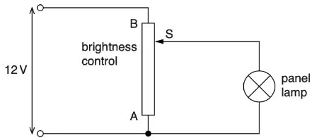
State the potential difference across the panel lamp when S is at end A.
0 V
6 V
12 V
It cannot be determined
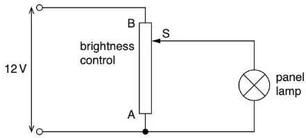
State the potential difference across the panel lamp when S is at end B.
0 V
6 V
12 V
It cannot be determined
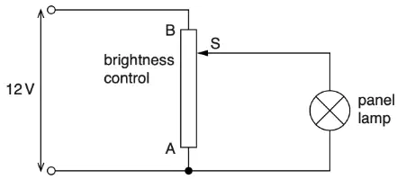
Describe what happens to the brightness of the lamp as S is moved from A to B.
Increases
Decreases
Remains unchanged
Flashes on and off
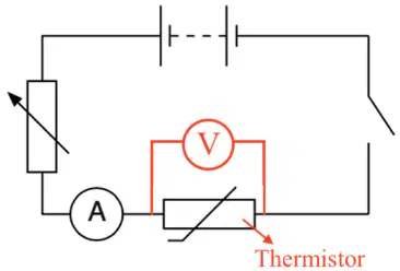
A student investigates how the resistance of a thermistor changes with temperature. In Fig. 9.1, label the thermistor in the circuit.
The lower right component in series with the circuit
The ammeter marked A
The power supply at the top
The dashed rectangular component at the top
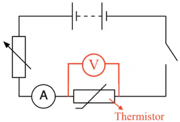
On Fig. 9.1, draw a voltmeter connected so that the resistance of the thermistor can be determined. How should the voltmeter be connected relative to the thermistor?
Across the thermistor in parallel
In series with the thermistor
Across the ammeter
In series with the ammeter
The potential difference across the thermistor is 6.0 V at 20 °C. Using Table 9.1 (current in the thermistor at 20 °C is 4.0 mA), calculate the resistance of the thermistor at 20 °C. Include the unit.
1500 Ω
150 Ω
2400 Ω
750 Ω
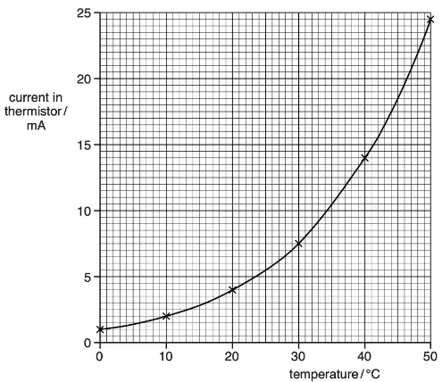
Fig. 9.2 shows a graph of current in the thermistor (mA) versus temperature (°C). The student suggests the current is directly proportional to temperature. Which statements from the graph show this suggestion is incorrect? Select all that apply.
It is a straight line through the origin
It is not a straight line
It does not pass through the origin
The graph is horizontal

