
 Worksheets
Capacitance and Capacitors Worksheet
Total questions: 99
Worksheet time: 50mins
What is capacitance in the context of an electrical circuit?
The property of a circuit or circuit component which allows it to store electrical energy in electrostatic form.
The ability of a circuit to generate magnetic fields.
The resistance of a circuit to the flow of current.
The property of a circuit to convert electrical energy into heat.
Which of the following is the standard unit of measurement for capacitance?
Farad
Ohm
Henry
Watt
A capacitor has a capacitance of one farad when:
A change of one volt across its plates results in the charge of one coulomb.
A change of one ampere across its plates results in the charge of one volt.
A change of one watt across its plates results in the charge of one coulomb.
A change of one ohm across its plates results in the charge of one ampere.
Which of the following is the correct value for one microfarad (μF) in terms of farads?
10−6 farads
10−3 farads
10−9 farads
10−12 farads
How can the capacitance of a capacitor be increased? (Select the best combination)
By increasing the plate area, decreasing the thickness of the dielectric, and using a dielectric with a high dielectric constant.
By decreasing the plate area, increasing the thickness of the dielectric, and using a dielectric with a low dielectric constant.
By increasing the plate area, increasing the thickness of the dielectric, and using a dielectric with a low dielectric constant.
By decreasing the plate area, decreasing the thickness of the dielectric, and using a dielectric with a low dielectric constant.
Which of the following is NOT a way to increase the capacitance of a capacitor?
Increasing the thickness of the dielectric.
Increasing the plate area.
Using a dielectric with a high dielectric constant.
Decreasing the distance between the plates.
Why might the farad be considered too large a unit for typical capacitors?
Most capacitors have much smaller capacitance values, so smaller units like microfarads, nanofarads, and picofarads are used.
The farad is only used for resistors.
The farad is not a standard unit.
Capacitors cannot store energy in farads.
What is one way to increase the capacitance of a capacitor according to the provided material?
Decreasing the number of plates
Increasing the number of plates
Reducing the plate area
Using thinner leads
What is the effect of increasing the number of plates in a capacitor?
It decreases the capacitance
It increases the capacitance
It has no effect on capacitance
It reduces the voltage rating
In a multi-plate capacitor, how are the alternate plates connected?
In series
In parallel or common
In a closed loop
To a ground only
Why are the plates in a multi-plate capacitor arranged to maximize plate area?
To reduce resistance
To increase capacitance
To lower the voltage
To minimize current

Based on the diagram, what is the main purpose of connecting alternate plates to each lead in a multi-plate capacitor?
To increase the resistance
To maximize the plate area and capacitance
To decrease the voltage
To reduce the number of leads required
What is the total capacitance when three capacitors of 30 μF, 10 μF, and 15 μF are connected in parallel?
55 μF
5 μF
20 μF
45 μF
Which formula correctly represents the total charge (Q_total) stored in a parallel capacitor circuit?
Q_total = VT x CT
Q_total = VT / CT
Q_total = CT / VT
Q_total = VT + CT
In a parallel capacitor circuit, how does the voltage across each capacitor compare to the total voltage?
The voltage across each capacitor is equal to the total voltage.
The voltage across each capacitor is half the total voltage.
The voltage across each capacitor is double the total voltage.
The voltage across each capacitor is zero.
If the total charge stored in a parallel circuit is needed, which of the following expressions is correct?
Q_total = QC1 + QC2 + QC3
Q_total = QC1 x QC2 x QC3
Q_total = QC1 - QC2 - QC3
Q_total = QC1 / QC2 / QC3

What is the correct relationship for the total capacitance (CT) in a parallel circuit?
CT = C1 + C2 + C3
CT = C1 x C2 x C3
(C1 + C2 + C3) / 3
CT = C1 - C2 + C3
When capacitors are connected in series, what is true about the charge on each capacitor?
Each capacitor has a different charge depending on its capacitance.
Each capacitor has the same charge in coulombs.
The charge is divided equally among the capacitors.
The charge is only present on the first capacitor in the series.
What happens to the total capacitance of a circuit when capacitors are connected in series?
It becomes equal to the largest individual capacitance.
It becomes equal to the smallest individual capacitance.
It is greater than the capacitance of any individual capacitor.
It is less than the capacitance of any individual capacitor.
Which equation correctly represents the total voltage across capacitors connected in series?
VT = VC1 × VC2 × VC3
VT = VC1 + VC2 + VC3
VT = VC1 - VC2 - VC3
VT = VC1 / VC2 / VC3

If three capacitors with values C1=30μF, C2=10μF, and C3=15μF are connected in series, which of the following statements is correct?
The total capacitance is equal to the sum of the three capacitances.
The total capacitance is greater than the largest individual capacitance.
The total capacitance is less than the smallest individual capacitance.
The total capacitance is equal to the average of the three capacitances.
Which of the following expressions correctly relates the voltage across each capacitor in a series circuit to the total charge and capacitance?
VC1 = QT × C1
VC1 = QT / C1
VC1 = C1 / QT
VC1 = QT + C1
What is the correct equation to calculate the total capacitance (C_T) in a series capacitive circuit with three capacitors?
1/C_T = 1/C_1 + 1/C_2 + 1/C_3
C_T = C_1 + C_2 + C_3
C_T = C_1 × C_2 × C_3
C_T = (C_1 + C_2 + C_3)/3
If three capacitors in series have values of 30μF, 10μF, and 15μF, what is the total capacitance of the series combination?
5μF
55μF
15μF
10μF
Which equation must be used to calculate the total capacitance in a parallel capacitive circuit?
C_T = C_1 + C_2 + C_3
1/C_T = 1/C_1 + 1/C_2 + 1/C_3
C_T = C_1 × C_2 × C_3
C_T = (C_1 + C_2 + C_3)/3
Why must the reciprocal equation be used for total capacitance in a series circuit?
Because the charge is the same on all capacitors in series.
Because the voltage is the same across all capacitors in series.
Because the total capacitance is always the sum of individual capacitances.
Because the capacitors are connected in parallel.
Given the equations for total capacitance in series and parallel circuits, how does the arrangement of capacitors affect the total capacitance?
Series arrangement decreases total capacitance, while parallel arrangement increases it.
Series arrangement increases total capacitance, while parallel arrangement decreases it.
Both arrangements always result in the same total capacitance.
The arrangement does not affect the total capacitance.

For the given circuit, calculate the total capacitance (C_T) when two capacitors, each with C₁ = 1 xF and C₂ = 1 xF, are connected in series.
0.5 xF
2 xF
1 xF
0 xF

For the given circuit, calculate the total capacitance (C_T) when two capacitors, each with C₁ = 1 xF and C₂ = 1 xF, are connected in parallel.
0.5 xF
2 xF
1 xF
0 xF
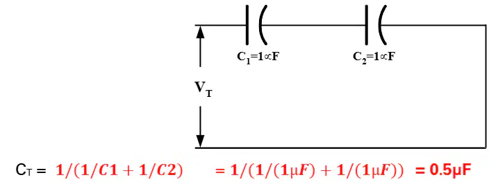
What is the total capacitance (Cₜ) when two capacitors, each of 1μF, are connected in series?
0.5μF
1μF
2μF
1.5μF

What is the total capacitance (Cₜ) when two capacitors, each of 1μF, are connected in parallel?
0.5μF
1μF
2μF
1.5μF
Which formula is used to calculate the total capacitance (Cₜ) of two capacitors in series?
Cₜ = C₁ + C₂
Cₜ = 1/(1/C₁ + 1/C₂)
Cₜ = C₁ × C₂
Cₜ = C₁ - C₂
If C₁ = 1μF and C₂ = 1μF, what is the value of Cₜ when they are connected in parallel?
0.5μF
1μF
2μF
1.5μF
Explain why the total capacitance of two capacitors in series is less than the value of either capacitor.
Because the voltage is divided equally.
Because the charge is doubled.
Because the reciprocal of the sum of reciprocals is always less than the smallest value.
Because the capacitors are in parallel.
What is the main advantage of using Alternating Current (A.C.) over Direct Current (D.C.) for transmitting electrical energy over long distances?
It allows for simpler and more efficient transmission of power.
It requires larger batteries and conductors.
It keeps the voltage constant at all times.
It is more costly and difficult to implement.
Which of the following best describes an A.C. voltage?
A voltage that continually changes in magnitude and periodically reverses polarity.
A voltage that remains constant in magnitude and polarity.
A voltage that only increases in magnitude.
A voltage that only decreases in magnitude.
Why would using a D.C. voltage source for national power transmission be difficult and costly?
Because batteries and conductors would have to be very big and all voltages would have to be essentially the same.
Because D.C. voltage cannot be generated in power stations.
Because D.C. voltage is more efficient than A.C. voltage.
Because D.C. voltage is only used for small electronic devices.
What does the vertical axis represent in the diagram of an A.C. voltage waveform?
The changes in magnitude of the voltage.
The time elapsed during one cycle.
The frequency of the voltage.
The resistance in the circuit.
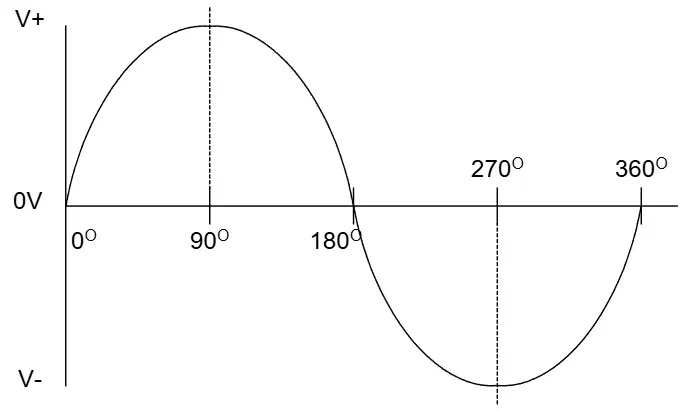
What does the horizontal axis in the A.C. voltage waveform diagram represent?
The time or phase angle in degrees.
The magnitude of the voltage.
The frequency of the current.
The resistance of the conductor.
What is a Single Phase System?
A system energized by a single alternating voltage.
A system energized by three alternating voltages.
A system energized by two or more alternating voltages.
A system energized by direct current.
Which of the following best describes a Poly Phase System?
A system energized by two, three or more alternating voltages.
A system energized by a single alternating voltage.
A system energized by direct current.
A system energized by only three alternating voltages.
A Three Phase System is characterized by which of the following?
Three equal alternating voltages 120° apart.
Two alternating voltages 90° apart.
A single alternating voltage.
Three unequal alternating voltages.
What does Line Voltage (V_L) refer to?
The voltage measured between terminals of an alternator, motor or branch circuit feeder wires.
The voltage measured across a phase of an alternator.
The voltage of a single phase system.
The voltage between two resistors in a circuit.
In the context of electrical systems, what is a Phase?
Each winding of an alternator, of a motor, or of a branch circuit forming part of a load.
The voltage measured between two terminals.
A type of electrical resistance.
A type of electrical current.
How is Phase Voltage (V_ph) defined?
The voltage measured across a phase of an alternator, motor or load.
The voltage measured between two resistors.
The voltage of a single phase system.
The voltage measured between two batteries.
Which coil in a transformer receives energy from the AC source?
The secondary coil
The primary coil
The core
The load
What is the main function of magnetic coupling in a transformer?
To increase the voltage
To transfer electric energy from one coil to another
To cool the transformer
To insulate the coils
What material is commonly used for the core of transformers operating at low frequencies?
Cardboard
Plastic
Sheet steel
Powdered iron
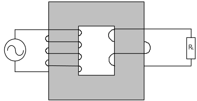
If a transformer is ideal, what is true about the transfer of energy from one voltage to another?
There are significant losses
There are no losses
The energy is doubled
The energy is halved
According to the voltage relationship in transformers, which formula correctly expresses the relationship between voltage and number of turns?
V_pri / V_sec = N_sec / N_pri
V_pri / V_sec = N_pri / N_sec
V_pri * V_sec = N_pri * N_sec
V_pri + V_sec = N_pri + N_sec
A transformer has 200 turns on the primary coil and 100 turns on the secondary coil. If the primary voltage is 240 V, what is the secondary voltage under ideal conditions?
120 V
240 V
480 V
60 V
Why might some transformer coils be wound on nonmagnetic hollow forms such as cardboard or plastic?
To increase the voltage
To reduce the weight and cost when a magnetic core is not needed
To improve magnetic coupling
To increase the number of turns
Which of the following best describes a step-up transformer?
A transformer where the secondary voltage is less than the primary voltage.
A transformer where the secondary voltage is equal to the primary voltage.
A transformer where the secondary voltage is greater than the primary voltage.
A transformer that only works with direct current.
If a transformer has a voltage ratio of 1:4, what does this mean?
For every 4 volts on the primary, there is 1 volt on the secondary.
For every 1 volt on the primary, there are 4 volts on the secondary.
For every 4 volts on the secondary, there is 1 volt on the primary.
For every 1 volt on the secondary, there are 4 volts on the primary.
What is the current relationship in the coils of a transformer?
The current is directly proportional to the voltage.
The current is inversely proportional to the voltage.
The current is equal in both coils.
The current is unrelated to the voltage.
Which formula correctly expresses the current and voltage relationship in a transformer?
V_pri × V_sec = I_pri × I_sec
V_pri / V_sec = I_sec / I_pri
V_pri / V_sec = I_pri / I_sec
V_pri + V_sec = I_pri + I_sec
What does the efficiency of a transformer compare?
The voltage of the primary and secondary coils.
The current in the primary and secondary coils.
The power output of the secondary winding to the power input of the primary winding.
The resistance of the coils.
Why is the efficiency of even the best practical transformer less than 100%?
Because of core and copper losses.
Because transformers use batteries.
Because transformers are always overloaded.
Because transformers do not use electricity.
A transformer has a power input of 1000 W and a power output of 900 W. What is its efficiency?
90%
100%
80%
110%
If the voltage on the primary coil of a transformer is 120 V and the voltage on the secondary coil is 480 V, what type of transformer is it?
Step-down transformer
Step-up transformer
Isolation transformer
Auto transformer
What is the unit used to rate transformer capacity?
Kilo-volt-amperes (KVA)
Kilowatts (KW)
Amperes (A)
Volts (V)
Which letter is sometimes used to represent transformer rating?
P
S
T
V
For an ideal transformer, what assumption is made about efficiency?
50%
75%
100%
90%
Which of the following equations correctly represents the relationship for the power input to the primary coil of an ideal transformer?
VA_sec = V_sec × I_sec
VA_pri = V_pri × I_pri
VA_pri = V_sec × I_sec
VA_sec = V_pri × I_pri
If the primary voltage (V_pri) is 240 V and the primary current (I_pri) is 5 A, what is the power input to the primary coil (VA_pri)?
1200 VA
48 VA
245 VA
235 VA
Explain why the output rating in kilowatts must specify the power factor in an AC circuit.
Because the power factor affects the voltage only
Because the power factor affects the current only
Because the power factor affects both the load and the current in the load
Because the power factor is not relevant in AC circuits
Which of the following best describes VA_sec in the context of transformers?
Power input to the primary coil
Power output from the secondary coil
Secondary voltage
Secondary current
Given the relationships for an ideal transformer, what can be said about VA_pri and VA_sec?
VA_pri is always greater than VA_sec
VA_pri is always less than VA_sec
VA_pri equals VA_sec
VA_pri is unrelated to VA_sec
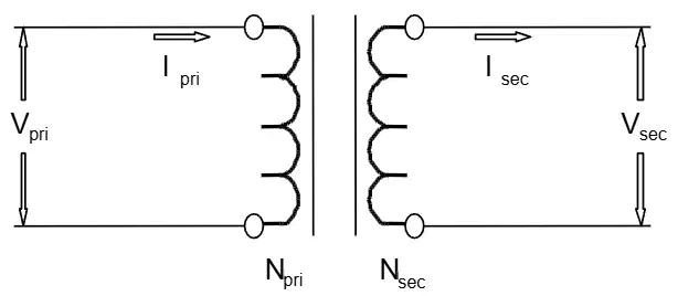
Given: Npri = 1500 turns, Nsec = 1000 turns, Vpri = 100 V. What is Vsec?
66.7 V
150 V
1000 V
15 V
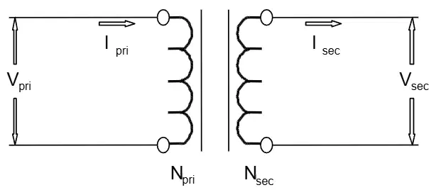
Given: Npri = 4000 turns, Nsec = 400 turns, Isec = 6 A. What is Ipri?
0.6 A
60 A
0.1 A
1.5 A
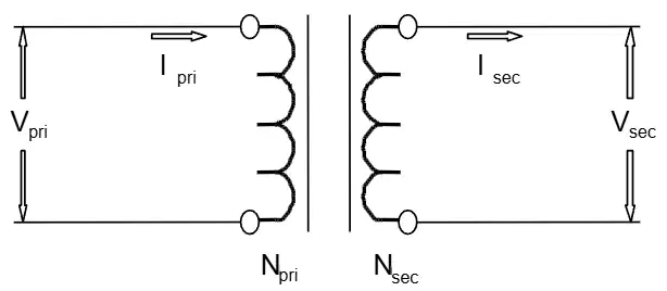
Given: Npri = 4000 turns, Nsec = 400 turns. What is the turn’s ratio?
10:1
1:10
4:1
1:4
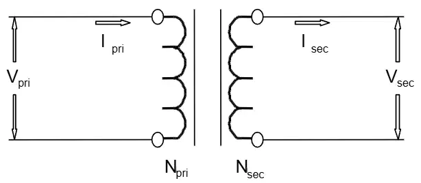
Given: Vpri = 300 V, Vsec = 24 V, Isec = 1 A, Npri = 1000 turns. What is Nsec?
80 turns
125 turns
24 turns
300 turns

Given: Vpri = 300 V, Vsec = 24 V, Isec = 1 A. What is Ipri?
0.08 A
1.25 A
12.5 A
0.5 A
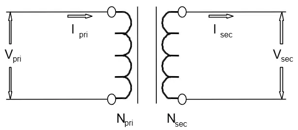
Given: VApri = 100, Vpri = 460 V, Vsec = 110 V. What is Ipri?
0.217 A
4.6 A
0.11 A
1.1 A
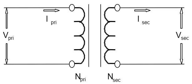
Given: VApri = 100, Vpri = 460 V, Vsec = 110 V. What is Isec?
0.91 A
1.1 A
0.217 A
0.24 A
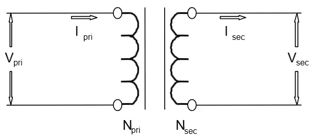
What is the secondary voltage (V_sec) if the primary voltage (V_pri) is 100 V, the number of primary turns (N_pri) is 1500, and the number of secondary turns (N_sec) is 1000?
66.667 V
150 V
100 V
50 V
If a transformer has 4000 primary turns, 400 secondary turns, and a secondary current (I_sec) of 6 A, what is the primary current (I_pri)?
0.6 A
6 A
60 A
1.5 A
What is the turn’s ratio for a transformer with 4000 primary turns and 400 secondary turns?
10:1
1:10
4:1
1:4
Given a transformer with a primary voltage (V_pri) of 300 V, a secondary voltage (V_sec) of 24 V, a secondary current (I_sec) of 1 A, and 1000 primary turns (N_pri), how many secondary turns (N_sec) are there?
80 turns
100 turns
240 turns
125 turns
If the apparent power (VA_pri) is 100 VA, the primary voltage (V_pri) is 460 V, what is the primary current (I_pri)?
0.217 A
0.909 A
2.17 A
0.046 A
A transformer has a secondary voltage (V_sec) of 110 V and an apparent power (VA_sec) of 100 VA. What is the secondary current (I_sec)?
0.909 A
0.217 A
1.1 A
0.11 A
If you increase the number of secondary turns in a transformer while keeping the primary turns and voltage constant, what happens to the secondary voltage?
It increases
It decreases
It stays the same
It becomes zero
A transformer is designed to step down voltage from 300 V to 24 V. If the primary winding has 1000 turns, explain how you would determine the number of secondary turns required and calculate the value.
Use the ratio N_sec = N_pri * V_sec / V_pri; N_sec = 1000 * 24 / 300 = 80 turns
Use the ratio N_sec = N_pri * V_pri / V_sec; N_sec = 1000 * 300 / 24 = 12,500 turns
Use the ratio N_sec = N_pri / (V_sec * V_pri); N_sec = 1000 / (24 * 300) = 0.139 turns
Use the ratio N_sec = N_pri + V_sec / V_pri; N_sec = 1000 + 24 / 300 = 1000.08 turns

What is the relationship between line voltage (VL) and phase voltage (Vph) in a Wye configuration?
VL = Vph
VL = 2 × Vph
VL = √3 × Vph
VL = Vph / √3
In a Wye configuration, how does the line current (IL) relate to the phase current (Iph)?
IL = Iph
IL = √3 × Iph
IL = Iph / √3
IL = 2 × Iph
If the line voltage (VL) in a Wye configuration is 300 V, what is the phase voltage (Vph)?
300 V
300 × √3 V
300 / √3 V
150 V
Why is the line voltage (VL) in a Wye configuration larger than the phase voltage (Vph)?
Because the line voltage is connected across two windings.
Because the phase voltage is always higher.
Because the line current splits in the phase winding.
Because the generator produces more voltage in the line.
A student claims that in a Wye configuration, the line current splits as it enters the phase winding. Is this correct? Explain your answer.
Yes, because the current always splits in three-phase systems.
No, because the line current is equal to the phase current in a Wye configuration.
Yes, because the voltage is higher in the line.
No, because the line current is always zero.
Which of the following best describes a three phase (3φ) system?
A combination of three single phase (1φ) systems.
A system with only one voltage waveform.
A direct current system with three wires.
A system that does not use alternating current.
In a balanced three phase (3φ) system, what is the phase difference between each of the three voltages?
120 degrees
90 degrees
60 degrees
180 degrees
What happens to the other two voltages in a three phase system when one voltage is at its maximum value?
Each of the other two voltages will be at 50 percent of their maximum value in the opposite direction.
Both voltages will be at their maximum value as well.
The other two voltages will be zero.
The other two voltages will be at 75 percent of their maximum value.
Why is most generation and distribution of alternating current done using three phase (3φ) systems rather than single phase (1φ) systems?
Three phase systems provide more efficient and balanced power distribution.
Single phase systems are more expensive to operate.
Three phase systems are only used for small household appliances.
Single phase systems cannot be generated by AC generators.
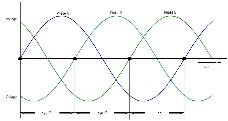
What does the diagram illustrate about the relationship between the three phases in a three phase system?
Each phase is separated by 120 degrees and reaches its maximum at different times.
All phases reach their maximum at the same time.
The phases are separated by 90 degrees.
Only one phase is present at any given time.
Which of the following is an advantage of a 3-phase (3φ) system compared to a single-phase (1φ) system?
3φ circuits require more weight of conductors than 1φ circuits of the same power rating.
3φ equipment is larger and heavier than 1φ machinery of the same rated capacity.
3φ circuits permit flexibility in the choice of voltages.
3φ circuits cannot be used for 1φ loads.
In a 3-phase system, what is the configuration called when the three common ends of each phase are connected together at a common terminal marked N for neutral?
Delta or Δ-connected
Wye or Y-connected
Series-parallel connected
Zigzag connected
What is the main difference between a Wye (Y) connection and a Delta (Δ) connection in a 3-phase system?
Wye is connected in parallel, Delta is connected in series.
Wye is connected in series, Delta is connected in parallel.
Wye has no neutral, Delta always has a neutral.
Wye and Delta are identical in configuration.

What does the neutral point in a Wye (Y) connection allow for in a 3-phase system?
It allows the system to be connected in parallel only.
It provides a common return path and can form a 3φ, 4-wire system.
It increases the weight of conductors required.
It prevents the use of 1φ loads.
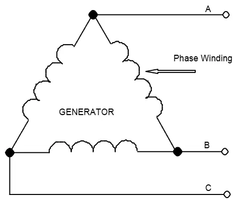
Which statement best describes a Delta (Δ) connection in a 3-phase system?
The three phases are connected to a common neutral point.
The three phases are connected in a closed loop, forming a parallel configuration.
The system cannot be used for 1φ loads.
The configuration is only used for low voltage applications.
Which of the following is the correct formula for real power (P_real) in a three-phase wye configuration?
PReal=3⋅VL⋅IL⋅cosθ
PReal=VL⋅IL
P_{Real} = 3⋅VL⋅IL⋅sinθ
PReal=VL⋅IL⋅sinθ

