
 Worksheets
Drainage 1 6035
Total questions: 47
Worksheet time: 24mins
Which document covers drainage and waste disposal?
Document L
Document G
Document F
Document H
Which BS number covers gravity drainage systems?
BS EN 12056
BS 1010
BS 1212
BS 8000
State which BS number covers good workmanship on site.
BS EN 12056
BS 6465
BS 422
BS 8000
Identify which BS EN number covers sanitary installations selection and maintenance.
BS EN 12056
BS 6465
BS 422
BS 806
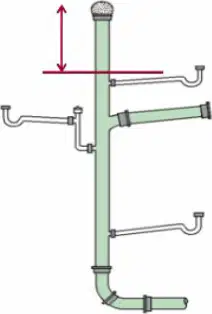
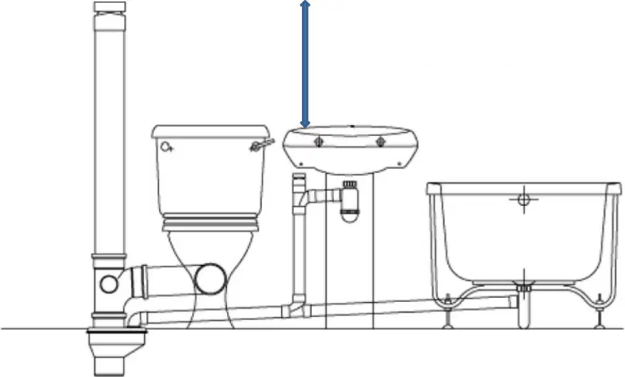
Identify the section of pipe shown in the diagram. The figure shows a vertical soil stack with an open end at the top above all branch connections and a red arrow pointing upward.
Stack vent (dry part above highest connection)
Discharge branch
Soil stack (wet part)
Trap weir
State the reason for a trap on an appliance.
To prevent foul air from the drainage system entering the room by maintaining a water seal
To increase flow velocity in waste pipes
To reduce water consumption
To provide mechanical support for pipes
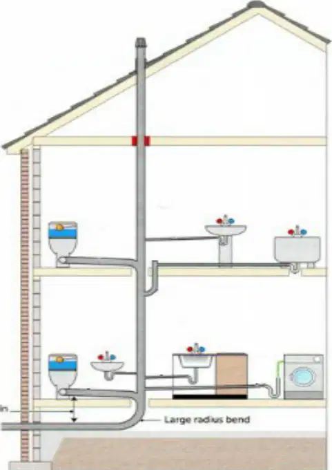
Identify from the diagram the type of soil stack system. The figure shows multiple appliances discharging to a single vertical stack that is vented at the top, with no separate individual vent pipes.
Single-stack system
Fully ventilated system with separate vents to each appliance
Primary Ventilated Stack
Combined rainwater and soil stack system

From the chart shown, identify the waste pipe size commonly used for a bath.
32 mm
40 mm
50 mm
75 mm

From the chart shown, identify the trap seal depth typically required for a sink.
25 mm
38 mm
50 mm
75 mm
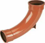
Identify the reason for and typical location of the bend shown. The image shows a long-radius bend used on a soil stack.
Used at the base of the soil stack to reduce flow disturbance and blockage risk when turning into the drain
Installed at the top of the stack to terminate the vent
Used only on small branch pipes to connect traps
Installed inside appliances to create a water seal
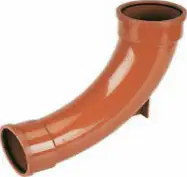
State which fittings could be used instead of the long-radius bend shown.
Two 45° bends installed to create a swept change of direction
A single 90° square bend
Three 22.5° bends installed tightly together
A trap fitted on the branch
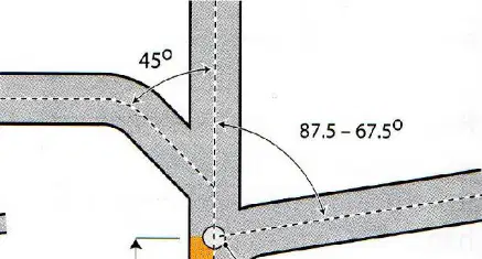
From the image, identify the permitted connection angle for branches up to 75 mm diameter when joining a soil stack.
90° square tee
Swept connection at 87.5° to 67.5°
Horizontal 180° connection
Only vertical in-line
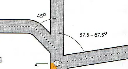
From the image, identify the preferred connection angle for branches over 75 mm diameter when joining a soil stack.
90° square tee
45° swept tee
22.5° only
Horizontal saddle connection
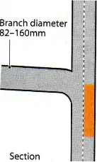
State the minimum distance you can make a connection from a branch on the opposite side of the stack to prevent crossflow contamination.
50 mm
100 mm
150 mm
200 mm
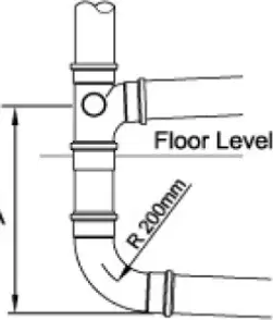
Identify the measurements for the lowest connections for a soil stack on a two-storey building up to a five-storey building. Select the correct pair.
450 mm for low level (2 storeys); 750 mm minimum for multi-storey (up to 5 storeys)
200 mm for low level; 300 mm minimum for multi-storey
600 mm for low level; 900 mm minimum for multi-storey
750 mm for low level; 1100 mm minimum for multi-storey
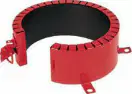
Identify the component shown and give a brief description of its purpose. The image shows a red ring with latches fitted around a plastic pipe.
Intumescent fire collar to maintain compartmentation by sealing plastic pipes during a fire
Pipe clamp for structural support of stacks
Flexible coupling for joining misaligned pipes
Access plug for rodding

Identify the components shown: top-left image (a strap-on boss and blanking plug).
Strap-on boss with blanking plug
Compression elbow
Trap adapter
Pipe hanger
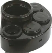
Identify the component shown: top-right image (a multi-entry boss for connecting small wastes to a stack).
Multi-entry boss (boss manifold)
Reducer coupling
Vent cowl
Access cap

Identify the component shown: middle-left image (a multi-branch manifold).
Multi-branch manifold (socket boss)
Pipe cap
Trap
Coupling
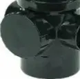
Identify the component and state where and why you would install it on a soil stack. The image shows an access pipe with a removable cap on the side socket.
Access pipe installed at changes of direction or at the base of the stack to allow rodding/clearing blockages
Vent cowl installed at the top to prevent rain entry
Reducer fitted mid-stack to change pipe diameter
Cap installed to permanently seal unused branches
State what should be installed on every discharge branch to allow for clearing blockages.
An access/rodding point
A vent cowl
A water hammer arrester
A reducer
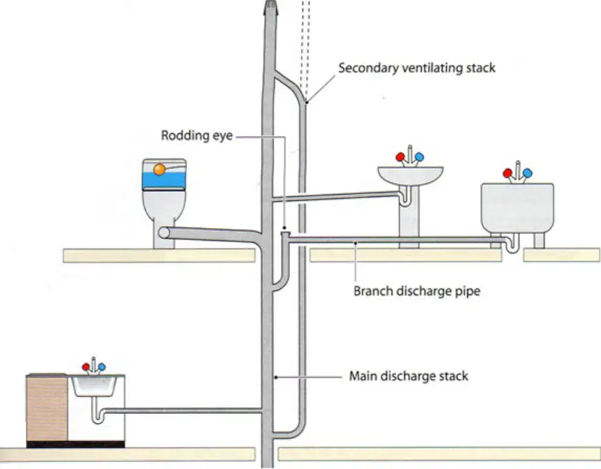
Identify the following soil stack type? The diagram shows a main discharge stack with branch discharge pipe, rodding eye, and a separate secondary ventilating stack rising alongside.
Single-stack system
Two-pipe system (secondary ventilated stack)
Waste-only stack
Pumped discharge system
State the minimum size of the secondary vent stack?
32 mm
50 mm
75 mm
100 mm
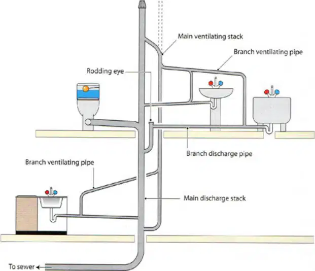
Identify the following soil stack type. The diagram shows a main ventilating stack with branch ventilating pipe(s), rodding eye, and branch discharge pipe(s).
Single-stack system
Fully ventilated (primary) stack system
Pumped discharge system
Septic tank vent only
Describe where you would install this type of soil stack?
In a small single-storey dwelling with very short branch runs
In multi-storey buildings where long branch discharge runs need additional ventilation
Only outdoors for stormwater drainage
In industrial process piping unrelated to sanitation
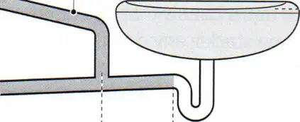
Identify the measuring indicated by the x above. The diagram shows a sink trap connected to a stack with a ventilation pipe; X marks the length between the trap outlet and the point where the branch ventilation connects.
Depth of the water seal in the trap
Vertical distance from appliance spill-over level to the vent connection
Developed length of the trap arm to the vent take-off
Diameter of the ventilation pipe
When installing a ventilated branch it must be installed at which height?
Below the trap weir
Level with the trap weir
Above the appliance spill-over level
At floor level
Identify the ventilated branch size to one appliance.
32 mm
40 mm
50 mm
75 mm
Identify the ventilated branch size for multiple appliances.
32 mm
40 mm
50 mm
75 mm
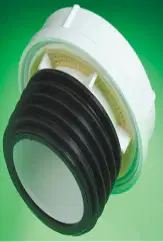
Identify the fitting shown and explain where you would use it. Image 1: a low-profile valve cap over a rubber coupling.
Air admittance valve used to ventilate an internal branch or stub stack where roof termination is not practical
Non-return valve to prevent backflow on pumped waste lines
Cleanout plug for rodding access
Inline water trap for a basin
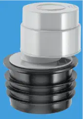
Identify the fitting shown and explain where you would use it. Image 2: a compact grey valve on a ribbed adaptor.
Air admittance valve for internal stack ventilation
Overflow relief gully for exterior installation
Gate valve for isolation on water supply
Vacuum breaker for hot-water cylinder
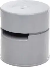
Identify the fitting shown and explain where you would use it. Image 3: a cylindrical vent cap with side slot.
Air admittance valve used to terminate a stub stack within a room
Pipe end cap for permanent sealing
Positive-pressure relief valve on a pump discharge
Trap primer device for floor drains
When the above fitting (air admittance valve) is installed, select three considerations you must apply.
Install at least 200mm above the spill-over level of the highest connected appliance
Locate in a ventilated, accessible space for inspection and maintenance
May be installed horizontally anywhere along the trap arm without restrictions
Provide frost protection and do not rely on it where positive pressure venting is required
Seal the room completely so no air can enter except via the valve
Identify the minimum gap from the spill-over level of the highest appliance when terminating with an AAV valve.
75mm
100mm
150mm
200mm
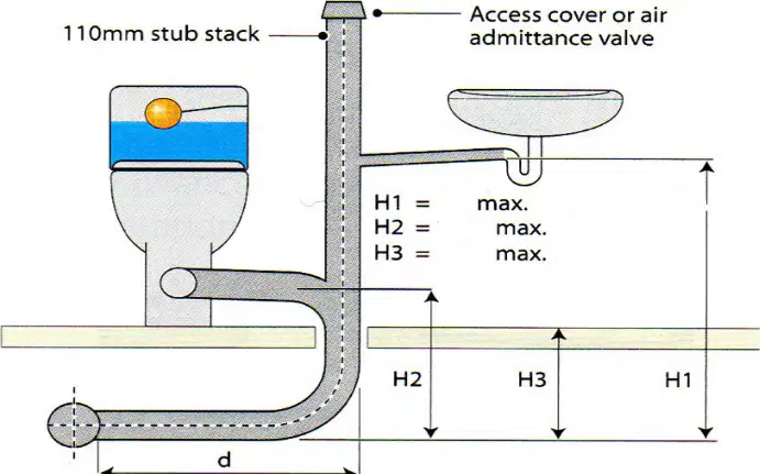
Identify the system shown below.
Stub stack system with air admittance valve
Single-stack system without ventilation
Two-pipe fully ventilated system
Pumped macerator discharge system
Select the statements that describe requirements for the system shown (stub stack).
Fit an access cover or air admittance valve at the top of the stub stack
Limit the heights of branch connections (H1, H2, H3) to prescribed maximums
Control the developed length d of the branch to a single appliance to the specified maximum
Provide the WC connection to a 110mm stub stack
Allow the stack to terminate below the spill-over level of connected appliances
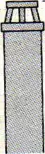
Identify the following measurements when terminating a soil stack within 3 m of an opening to a building: What minimum height above the opening must the vent termination be when the soil stack is within 3 m of that opening?
300 mm
600 mm
900 mm
1200 mm

Identify the following measurements when terminating a soil stack within 3 m of an opening to a building: What horizontal distance defines “within” proximity to the opening in this requirement?
1 m
2 m
3 m
4 m
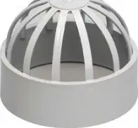
State where you would install the image shown (white domed cage) and why: What is the correct application for this terminal?
On top of a soil vent pipe at roof level to prevent birds and debris entering while allowing ventilation
Inside a kitchen extractor to diffuse airflow
Under a washbasin as a guard for a P-trap
In a rainwater downpipe to stop backflow into the gutter
State where you would install the image shown (black cage cowl) and why: What is the correct application for this terminal?
On a soil vent pipe termination to keep out birds while maintaining free airflow
At the base of a stack to act as a rodding eye
Inside a WC cistern as an anti-siphon valve
In a kitchen sink waste as a strainer
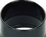
State where you would install the image shown (black cone adaptor) and why: What is the correct application for this fitting?
At the top of a soil vent pipe as a terminal adaptor/reducer to suit a cowl and shed rain
Inline on hot-water pipework as a venturi to increase flow
At the base of a rainwater downpipe as a gully trap
On a cold-water storage cistern overflow to prevent freezing
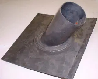
State where you would install the image shown (roof flashing with pipe penetration) and why: What is the correct application for this component?
Where a vent pipe passes through a roof to weatherproof the penetration and prevent leaks
Inside a soil pipe to act as a backflow preventer
Under a kitchen sink as a flexible connector
At the end of a rainwater gutter to form an outlet
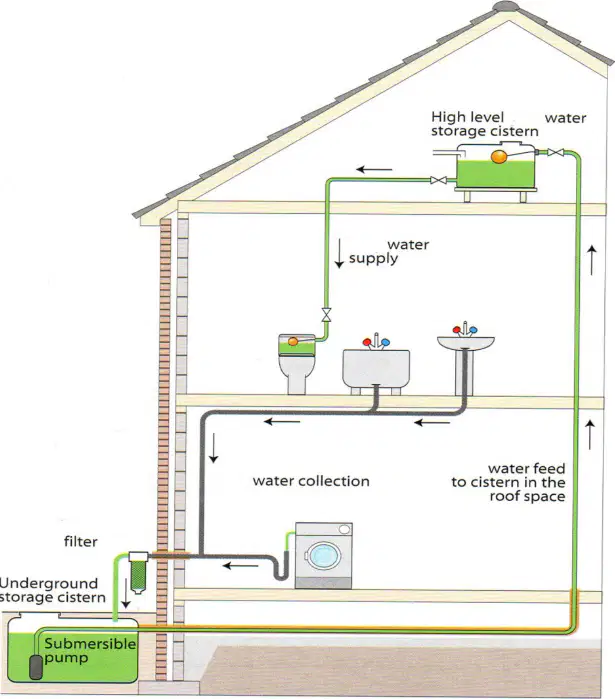
Identify the system below and its benefit: Based on the house diagram showing an underground storage cistern, a filter, a submersible pump, and a high-level storage cistern supplying non-potable fixtures, what system is illustrated?
Greywater recycling system
Central heating system
Rainwater downpipe system only
Septic tank effluent disposal system
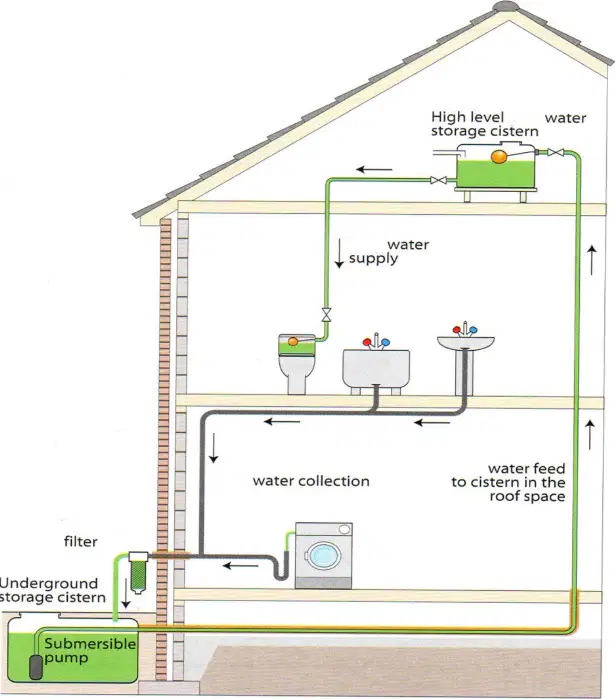
Identify the system below and its benefit: What is the primary benefit of the illustrated system for a dwelling?
Reduced consumption of potable mains water for toilet flushing and similar uses
Increased load on the sewer system
Improved indoor air quality by ventilation
Faster delivery of hot water to taps
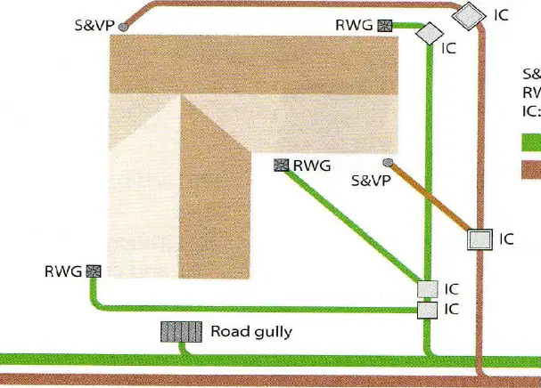
Identify the drainage system shown in the diagram, where green lines denote rain water drains discharging to a surface water sewer and brown lines denote foul water drains discharging to a foul water sewer.
Separate system
Partially separate system
Combined system

Identify the drainage system shown in the diagram, where both green rain water drains and brown foul water drains discharge to the same combined surface and foul water sewer.
Separate system
Partially separate system
Combined system
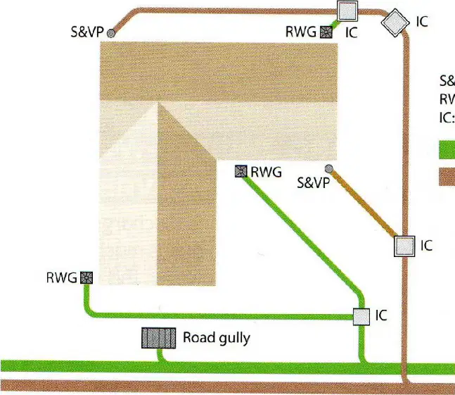
When installing a rain water pipe to a combined system, which fitting is used to make the connection?
Trapped gully
Untrapped gully
Direct branch into the foul drain without a trap
Open channel discharge to the combined sewer

