
 Worksheets
Modulo 1 sest parte 1
Total questions: 99
Worksheet time: 2hrs 39mins
A boiler burner fails each time it is started with failure indicated as "flame failure". Indicate the most likely reason.
The fan motor is faulty.
temperature is too high
The flame cell is dirty.
have the wrong output voltage.
The engine room high level bilge alarm keeps sounding every few minutes even though the bilge is empty. What action would you take?
on the alarm printed circuit board.
of the level switch and the printed
Disconnect the alarm and see if it helps.
Start the bilge pump.
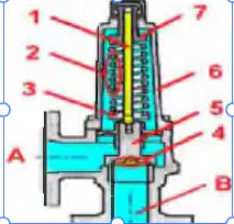
What is component number 3 called?
A spring adjuster.
A spring tensioning washer.
A valve cover.
A spring plate.
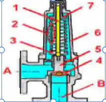
What is "chatter" in a safety valve?
The first leakage before the vaIve opens.
A failure of a safety valve to re-seat.
A metallic hammering noise.
A hissing sound indicating that a safety valve is leaking.
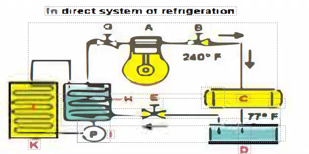
Which part is the brine cooler?
D
H
K
C
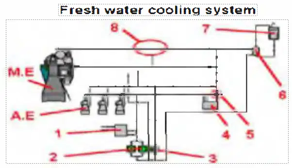
Should water be circulated through the main engine during a port stay, and if so why?
No, as this would result in extra water consumption from main engine water leaks.
Yes, as this will maintain watertight condition of hoses and connections.
Yes, circulating the auxiliary Jacket water will maintain the main engine temperature.
No, as this will prevent the auxiliary engines attaining the correct temperature.
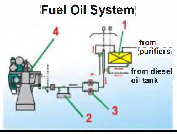
What is part number 1 called?
The drainage tank.
The expansion tank.
The service tank.
The settlement tank.
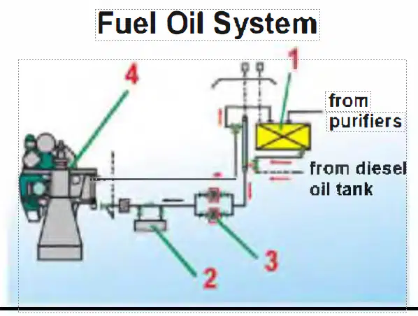
Which part is the heater?
Number 1
Number 2.
Number 3.
Number 4
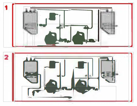
Which of the two drawings shows two series connected purifiers?
1
2
Neither.
Both 1 and 2.
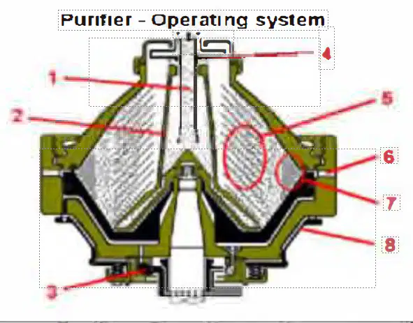
Where is the inlet for the unclean oil?
Area 1
Area 3.
Area 4
Area 6
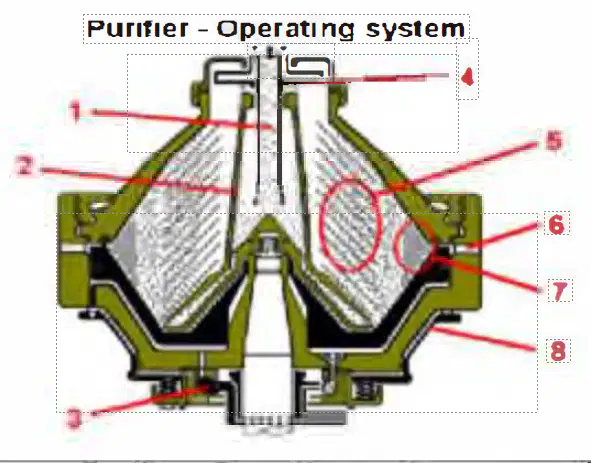
What is pare number 2 called?
The chamber
The paring disc.
The dfstrfbutor.
The bowl hood.
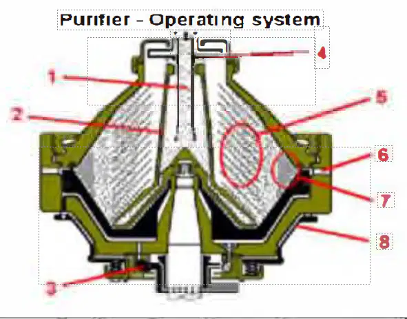
Which part is the paring disc?
Part2
Part3
Part4
Part6
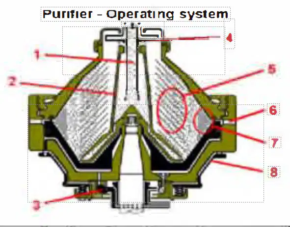
What is part number 3 called ?
The paring disc for processed oil.
The spring support.
Disc stack support bearing
The water paring disc.
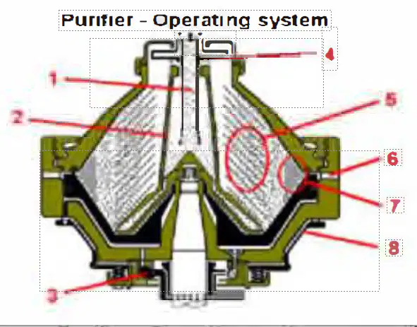
What is part number 5 called?
The disk holder.
The disc stack.
The paring disc.
The distributor vanes.
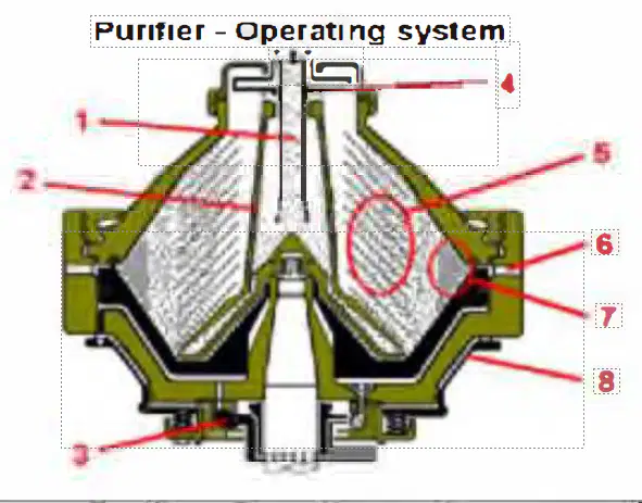
Where is the separation carried out?
Position number l
Position number 2.
Positioin number 7.
Position number 5
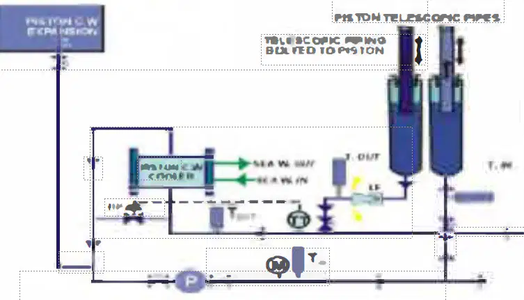
What kind of temperature control mode is fitted here?
Controlling outlet by regulating the inlet.
Controlling outlet by regulating the outlet.
Controlling inlet by regulating the inlet
Controlling inlet by regulating the outlet.
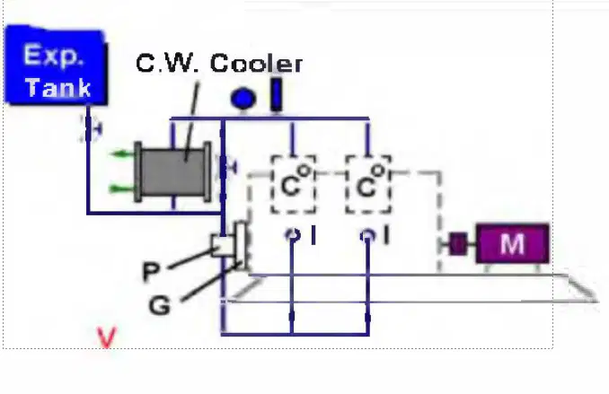
Which kind of cooling water system is used with this compressor?
Forced sea water cooling.
Open free flow sea water cooling.
Forced fresh water cooling
Free flow fresh water cooling.
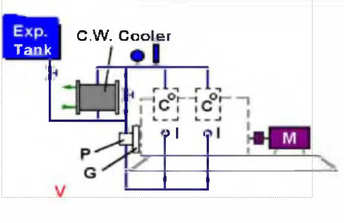
What is indicated by position "I" at both of the cylinders?
Water inlet of lntercoolers.
Water inlet of
cylinders/inter coolers.
Water inlet of cylinders.
Water inlet of aftercoolers.
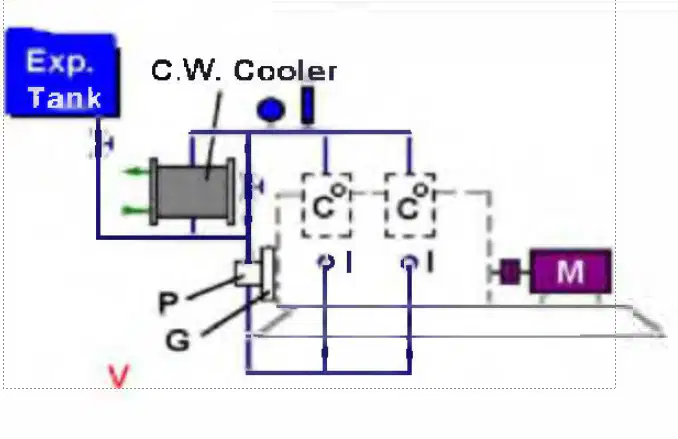
Suppose the delivery air pressure of this compressor is 30.0 bar. What class of compressor could this be?
A service air compressor .
An instrument air compressor.
A working air compressor.
A starting air compressor.

What are the units marked "C" fitted on both cylinders?
After coolers.
Intercool ers.
Cylinder blocks.
Cooling water vessels.
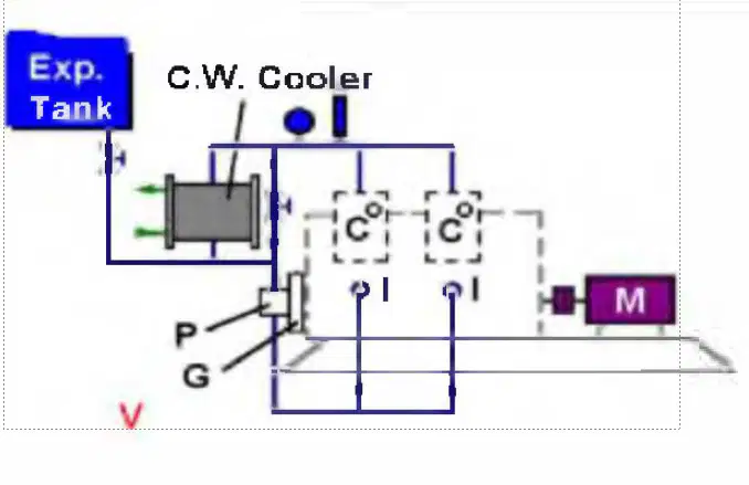
When is manual by-pass valve of this compressor cooler "CW" operated?
During normal running to keep the temperature constant.
In the case of a cooler tube leaking.
In cold climates to avoid moisture.
When the compressor is new/overhauled with new rings.
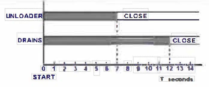
When starting a compressor. why is it necessary for the unloader to be activated before the drain valves are closed?
So the pumping action can blow the drains through.
To avoid the safety valves blowing.
To avoid air blowing in the bilges.
To prevent the compressor from tripping.
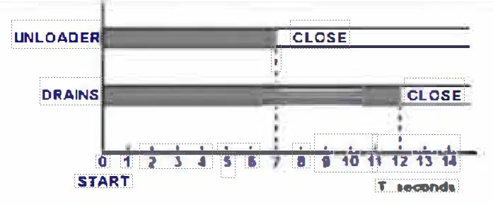
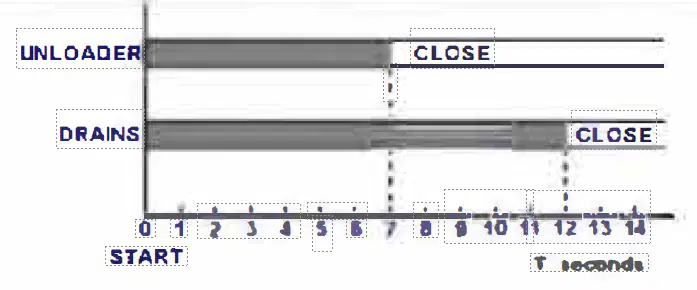
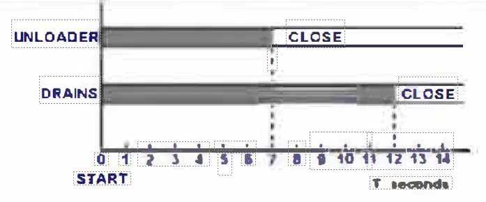
This drawing indicates the timing of the unloader and drains of a compressor. After how many seconds will the compressor pump at full capacity?
7 seconds.
12 seconds.
14 seconds.
Between 7 and 12 seconds.
Why is it necessary to start a compressor with the drains open?
To hear that it is delivering pressure and the unloader is working.
To get rid of all the dirt inside.
To blow clear any moisture from the compressor discharge.
To avoid overloading the electric motor.
On what part of the compressor does the unloader act and in what way?
It keeps the suction vaIves open.
It keeps the suctions valves closed.
It keeps the delivery valves open.
It keeps the delivery valves closed.
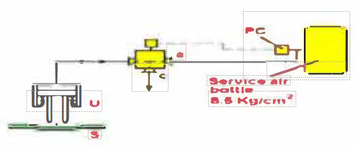
What would be the pressure in the air bottle which activates the "PC" and "S" connecting the unloader line with c and a ?
Between 6.5 and 8.5 bar.
Between 8.5 and 70.0 bar.
Between 0 and 8.5 bar
Between 8.5 and 9.35 bar.
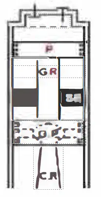
In which kind of compressor is this type of piston assembly fitted?
Refrigeration compressor.
CO2 compressor.
Service air compressor.
Oil-free instrument air compressor.
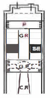
What is the purpose of the stuffing box in this combined piston compressor assembly?
To keep the air of the pumping space separated from the guide.
To prevent oil from being pumped up to the pumping piston.
As sealing between pumping cylinder and guide cylinder.
All of these options.
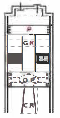
In this oil-free compressor, of what material are the piston rings of the pumping piston "P" made ?
Chrome plated.
Slotted chromium.
Plain cast iron.
Carbon.
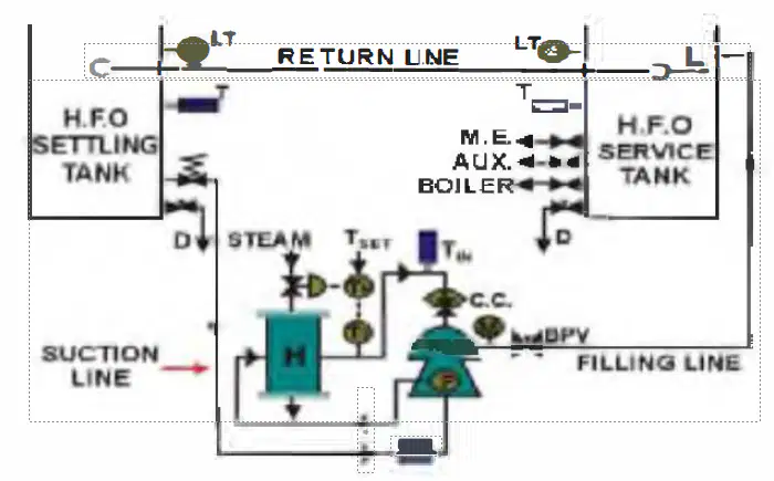
If you increase fuel flow to the purifier using capacity control valve CC, what other action must you take?
Increase the flow from the settling tank to the purifier.
Throttle steam to the H FO service tank.
Adjust back pressure with back pressure valve
Drain the service tank at shorter intervals.
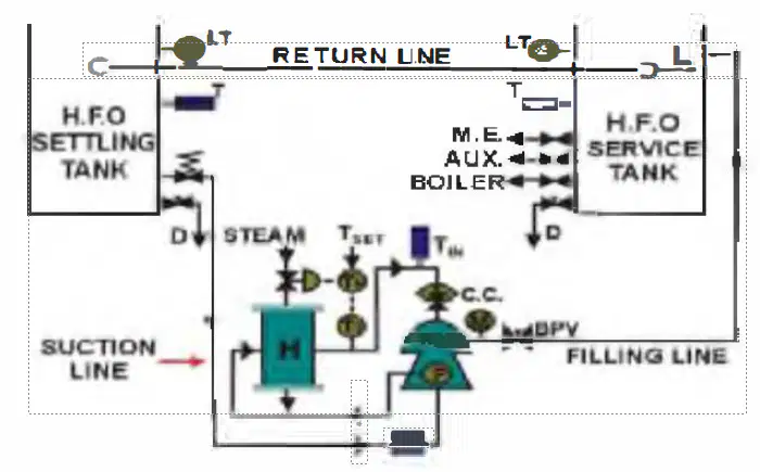
What type of pump is the HFO purifier feed pump P?
A centrifugal pump.
A gear pump or worm pump
A piston pump
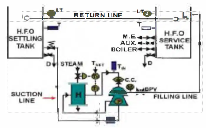
How is pump "P" driven from the purifier?
By V-belt.
By electric motor.
By shaft drive with replaceable sheer pins from the purifier crankcase.
By direc gear drive from the p11rifie1 crankcase.
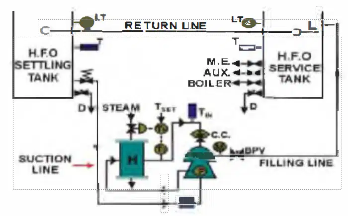
What is item "F"?
A flow meter.
A flow control device.
A normal mesh filter/strainer
A fuel shut-off solenoid.
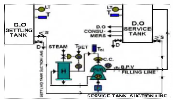
When using marine diesel oil with a density of about 0.87. what would be the inlet temperature of the fuel to the purifier?
30 degreeC.
40 degree C.
60 degreeC.
85 degree C.
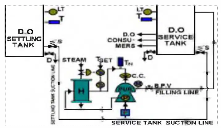
What is the ideal temperature to maintain the diesel oil daily tank and how is this achieved ?
45 degree C, by circulating the fuel with the purifier tank.
45 degree C, by application of steam heating.
65 degree C, by application of steam heating.
65 degree C, by circulating the fuel with the purifier tank.
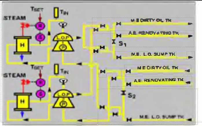
When you start a purifier it takes several minutes to accelerate to full speed since the power from the electric motor is transferred by to the purifier.
a plate clutch
a magnetic coupling
a centrifugal clutch
a rotating coupling
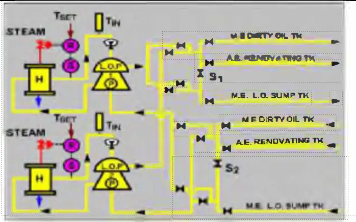
Which of the following alarms may sound after the automatic desludging cycle is completed and the purification of the oil restarts?
The overflow alarm.
The water seal alarm.
The oil high temperature alarm.
The oil high pressure alarm
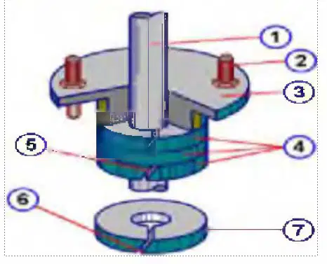
In what kind of machinery would this type of gland packing never be used?
Steam valve spindles.
Refrigerating installations.
Sea water or freshwater pumping equipment
Fuel oil or Lubricating oi I systems.
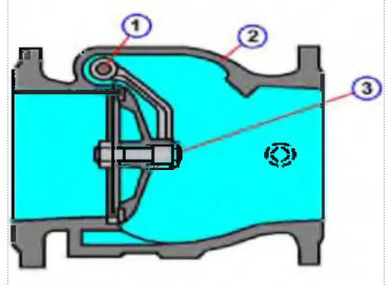
What do you call this device?
A safety lifting valve.
An overpressure blow-off valve.
A straight non-return valve.
A scavenge air valve.

What is the required temperature in the ship's fish room?
From 0 to - 5 degree C
From -20 to - 25 degree C
From -15 to - 20 degree C
From -5 to -70 degree C.
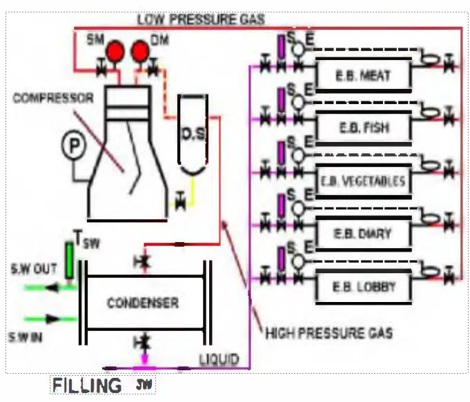
What is the required temperature in the ship's dairy room?
From 0 to +3 degree C
From +3 to +5 degree C
From -2 to +2 degree C
From +5 to +7 degree C
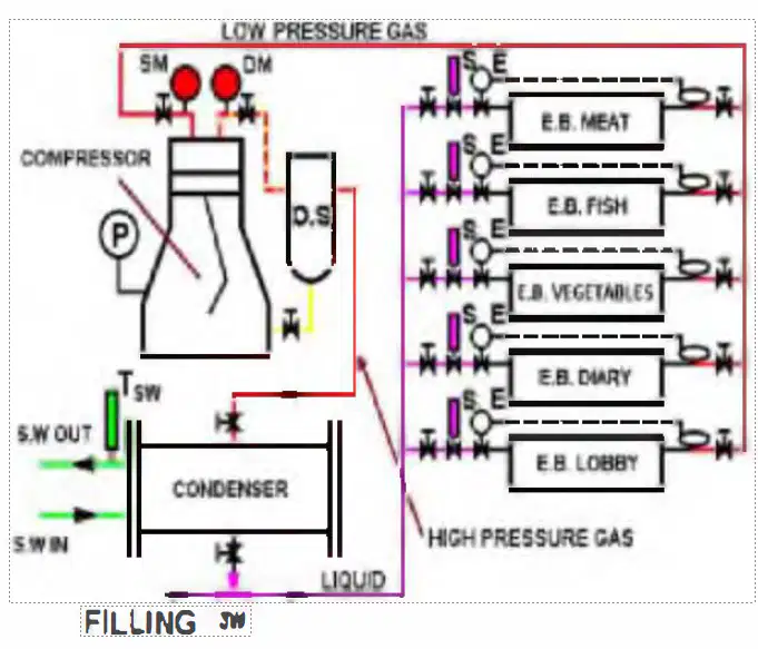
What is the required temperature in the ship's vegetable room?
From +2 to +4 degree C.
From +4 to +6 degree C.
From +5 to +7 degree C.
From +7 to +10 degree C.
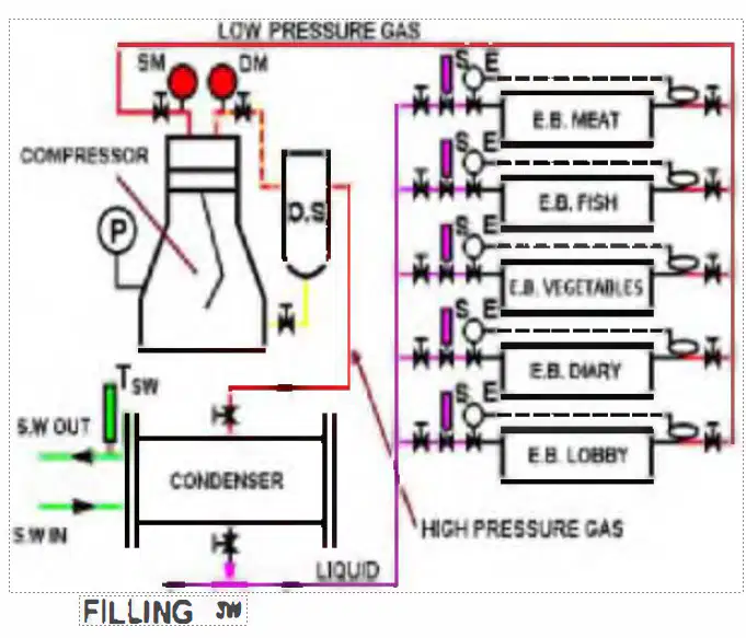
What parameter is controlling the capacity control system of this domestic refrigerating compressor?
The temperature in the refrigerated rooms.
The temperature and back-pressure of the condensor.
The suction pressure of the compressor.
The discharge pressure of the compressor.
Freon is being phased out gradually as a refrigerant. Why?
Because it is too expensive.
Because it is being replaced by more efficient refrigerants.
Because it has a damaging effect on the Earth's ozone layer.
Because under certain conditions it is toxic
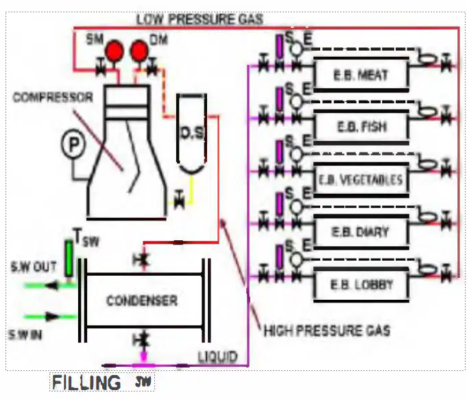
How are the solenoid valves "S" (fitted before the evaporating banks) controlled?
By the pressure of the evaporating liquid.
By the defrost control panel.
By the evaporator gas outlet temperature.
By the temperature inside the refrigerated compartments.
What is the state of the refrigerant which flows from the condenser to the solenoids and the expansion valves,
It is hot and undercooled.
It is under condenser pressure and undercooled.
It is below condenser pressure and condensed.
It rises above the condenser pressure and decreases in temperature.
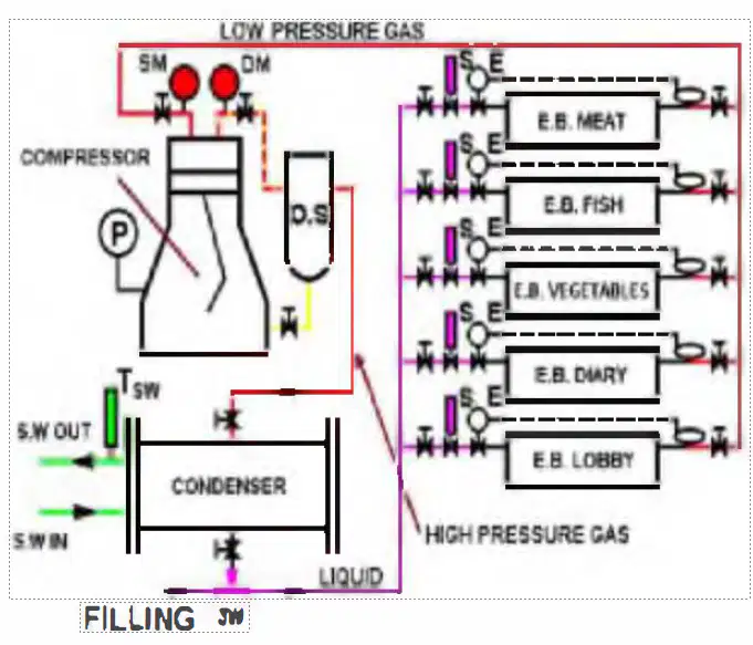
Why is there an oil separator "OS" fitted as shown here?
Because Freon absorbs oil and it needs to be separated.
To separate the oil dragged with the Freon from the compressor.
To separate oil during compressor start-up.
To collect the oil before stopping the compressor.
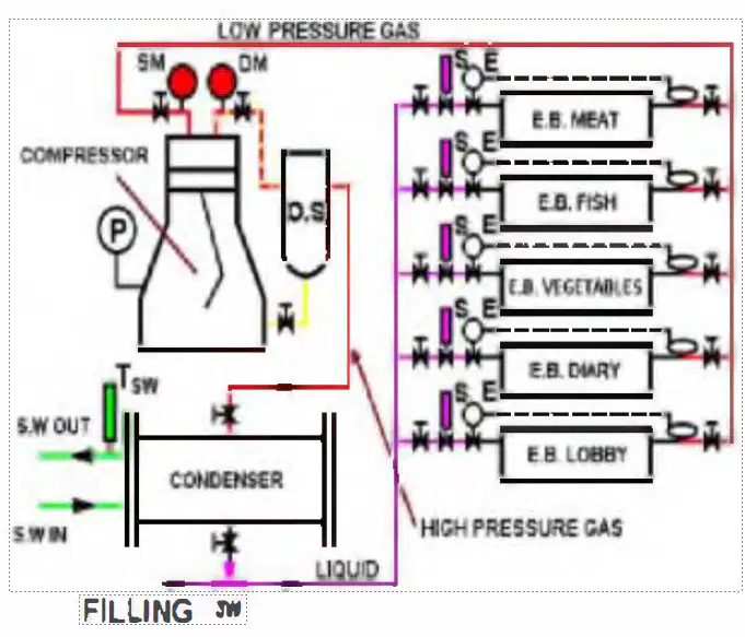
What is the function of the low pressure cut-out fitted on the same manometer line as manometer "SM" ?
As safety shut-down device. Inspection and reset are required.
Purely as cut-in/cutout device by low capacity. No reset required.
As safety power tripping device. Solenoids "S" will also close.
As alarm device only without shut-down function.
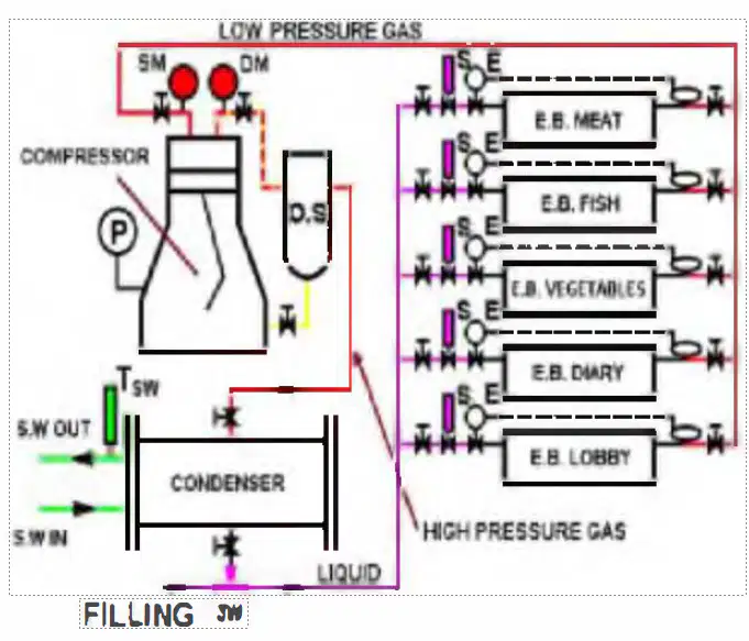
What is the function of the high pressure cut-out fitted on the same manometer pipe as manometer "DM" ?
As safety cut-out with additional alarm function. Manual reset required.
As operational cutout when condenser pressurised prolonged.
As electrical overload and alarm. auto reset.
As alarm device only.
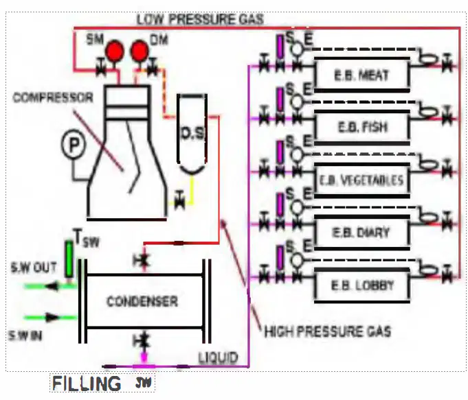
What is the function of the oil differential pressure cut-out fitted between the manometer pipes of manometers "P" and "SM"?
As temporary cutout
As high temperature warning.
As warning/cut out due to oil foaming.
As a low lub oil pressure cut-out
If during your watch the air-conditioning compressor cuts-out because of high discharge pressure. what are you going to check immediately?
If the
accommodation vent fan has tripped.
The level of the receiver. to see if the Freon has escaped.
That there is sufficient cooling water to the condenser.
Ice formation on the evaporating unit
Why is there a receiver fitted below the condenser of an air-conditioning unit unlike on the condenser of the domestic fridge system?
Because the airconditioning does not run in winter climates.
To store spare Freon.
Because there is more chance of leakage and Freon escape.
Because the capacity is larger.
You are notified that it is getting hot in the accommodation and the air conditioning is not working. What do you check immediately?
If the aircon compressor is still running.
If suction and discharge pressures on the compressor are normal.
If the accomodation vent fans are running.
If there is sufficient refrigerant in the system.
When should the recirculation of air from the accommodation be set to 100 % and the fresh air intake totally closed?
When outside temperature is more than 30 degree C
During cargo operations or cargo transfer in port or at sea.
When outside temperature is more than 36 degree C.
When vessel is moored at an oil refinery.
What is the most important item of maintenance required to ensure maximum efficiency of the accomodation air conditioning plant?
Clean the central air conditioning fan unit intake suction filters.
Ensure always that there is sufficient Freon in the receiver.
Ensure the evaporator unit remains ice free.
Clean the sea water side of the condenser every 2 months.
What kind of metal must never be allowed to come in contact with Freon liquid or Freon gas and why?
Chromium, it will overheat.
Iron, it will be rapidly wasted by the Freon.
Aluminium, it dissolves in contact with Freon.
Copper, it has a harmful effect on the Freon.
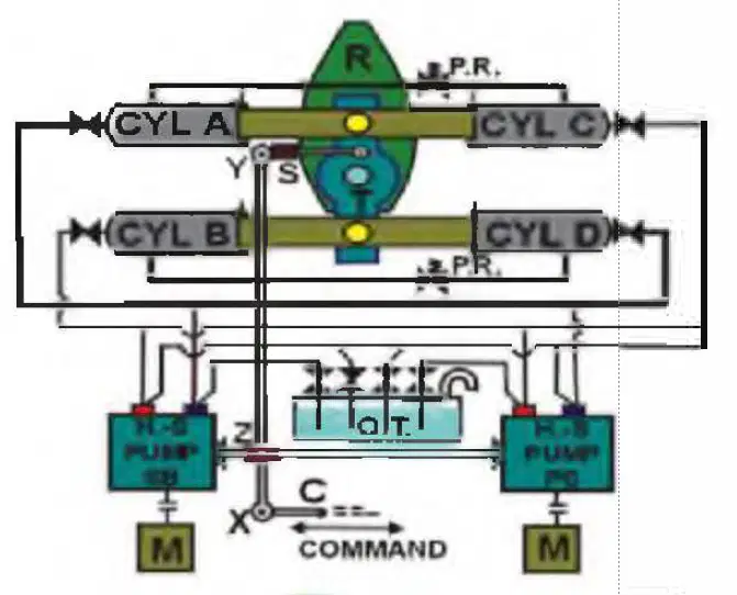
What type of pump is referred to in the drawing as an "H.S. PUMP"?
Higgins-Simpson pump.
Hydraulic solenoid pump.
Hele-Shaw pump.
High suction pump.
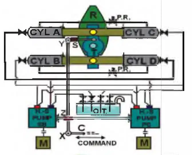
What is the function of the valves "PR" fitted between the Port and Starboard cylinders?
To return any excess oil back to the suction of the pump.
to act as automatic by-pass valves when the steering gear is stopped.
To be opened to allow emergency steering.
To relieve excess pressure, absorbing shock and preventing damage.
When will the Hele-Shaw pump commence pumping action?
As soon as the electric motor is started.
As soon as the pilot system is started on the bridge.
As soon as point "Z" moves.
As soon as the telemotor pump is started.
When a command is given to this steering gear, what happens ?
The spring "S" will be compressed or elongated
The valves "PR" will activate. building up hydraulic pressure.
Point "X" will move, in turn moving point "Z", controlling the pump delivery.
The hydraulic pumps will start.
What is the purpose of spring "S" fitted between point "Y" and the Trunion block of the steering gear?
To elongate and compress and keep point "Y" in place.
To absorb the clearance of the
Tr union with the rod
x-y
Ensuring flexibility by absorbing vibrations and clearances.
To avoid sudden movements and overload.
What is to be checked during a drydocking period to ensure that any upward movement of the rudder will be contained and damage to the steering gear will be avoided?
The rudder stock carrier bearing clearance.
The pallister bearing clearance.
The upper and lower pintlejumping bar clearances.
The pintle bearing clearances.
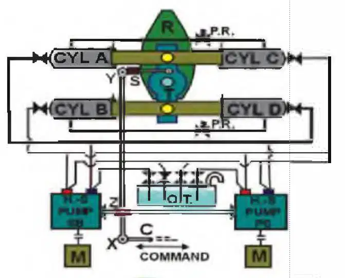
Which action of the steering gear pumps is feasible?
Pressure to cylinders A and D, return oil from B and C.
Pressure to cylinder A. return oil from D.
Pressure to cylinders A and B, return oil from C and D.
Pressure to cylinders A and C. return oil from B and D.
During normal operations, the command rod "C' pushes point "Z" and the control rod off centre so that the "HS" pumps start pumping and the steering gear moves. When will it stop moving?
When the command rod "C" stops moving.
When the command rod "C" moves in opposite direction.
When the trunion point "Y" pushes point "Z" back to its original position.
When the rudder angle indicator corresponds to the command.
What should you observe when inspecting the steering gear during your watch?
The oil level in the oil tank, see that there is no oil leakage.
The greasing of trunion and Pallister bearing is adequate.
No abnormal noise or vibrations, pump power consumption normal.
All of these options.
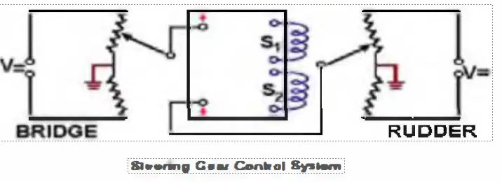
This electric circuit is part of the Steering Gear Control System. in which the output is either 1 or 0 as either solenoid 1 or 2 is energized. It is an example of what kind of circuit ?
A Wheatstone Bridge.
Two double resistor circuits balanced by the solenoids.
Two Potentiometers with amplifier relays.
A booster aggregate
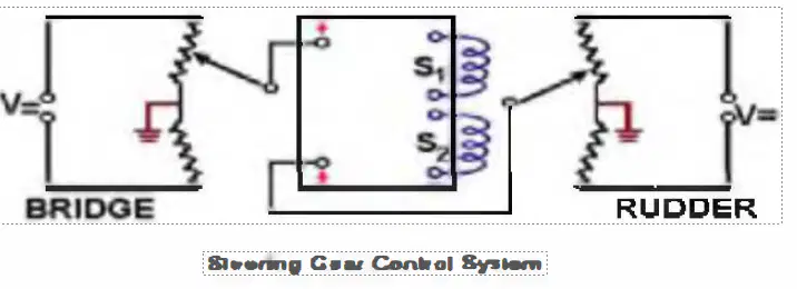
The first potentiometer of this electric command system is located on the bridge. By what mode might it be actuated.,
By hand steering.
By push button steering.
By utomatic steering via the auto-pilot.
By any of these steering rnethods.
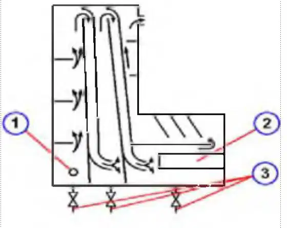
What is the principle in which oil/water separation takes place in this cascade tank?
By separation frames.
By directional change and centrifugal action in triple-action,
By acceleration through chambers.
By acceleration and gravitation.
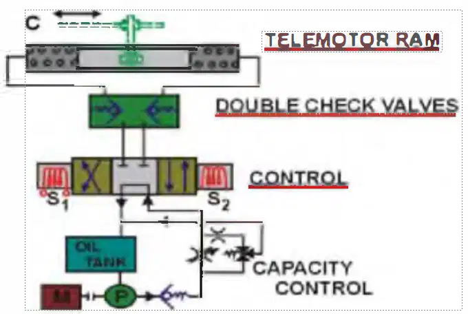
This steering gear telemotor system is drawn in the neutral position, rudder amidship. this means that...
pump 'P" is not pumping.
the double check valves ar blocked.
the capacity control is at z ro.
neither solenoid "S1" or "S2" is energised.
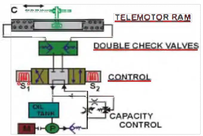
What is the purpose of the double check valves fitted in this telemotor system?
To keep the rudder locked in the desired position.
To maintain the set pressure in the system.
To avoid oil blockage and stickiness.
To avoid pipe rupture due to sudden movements.
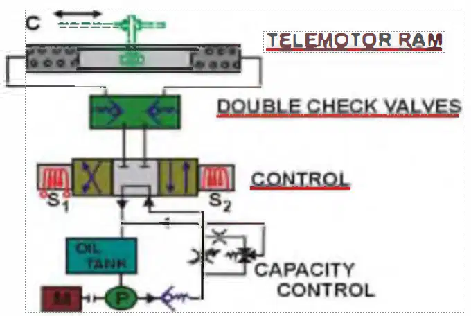
What is the purpose of the capacity control on the telemotor of a steering gear?
To keep the oil delivery quantity of the pump constant
To keep the outlet pressure and capacity to react constant
To keep the electric capacity between parameters
(absorption).
To keep the oil delivery quantity to the telemotor ram constant
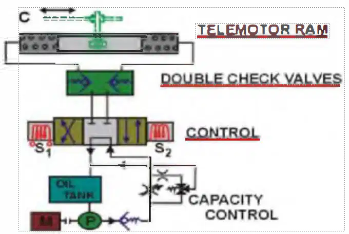
How might this steering system be actuated?
By automatic gyro steering.
By push-button steering
By hand steering
By any o these.
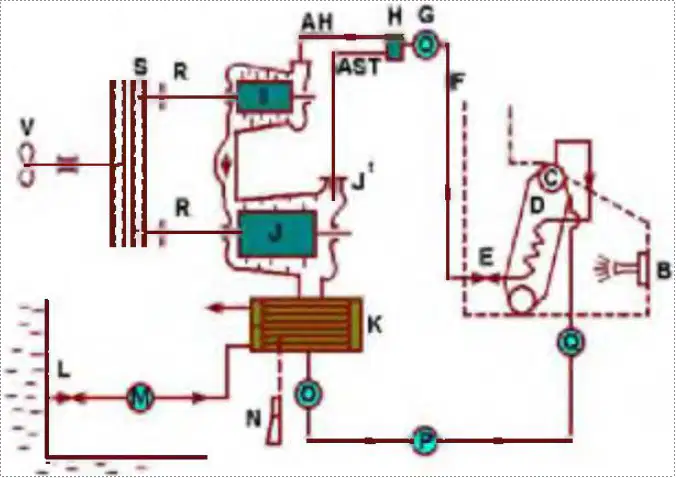
What type of boilers are fitted (one only shown) to feed this turbine installation,
Scotch type boilers.
Water tube boilers.
Cochran type boilers.
Exhaust dissipation boilers.
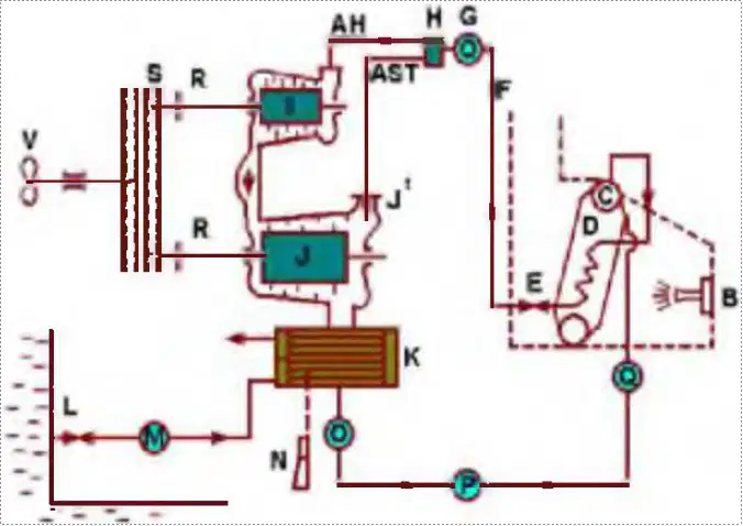
Item "H' of the drawing indicates ............................ of this turbine installation?
the distributor.
the steam filter.
the manoevring stand.
the steam reducer.
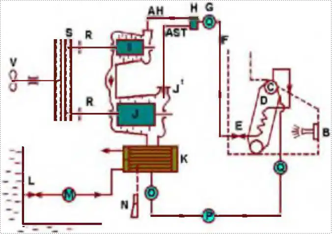
This installation consists of the following turbine combination.
a high pressure and a low pressure tur lne.
a turbine system wiU1 at1ead and ast rn ma oevri c pability.
the H.P anti LP turbine acllng in tandem Lo one reduction g ar
All of tt,ese options.
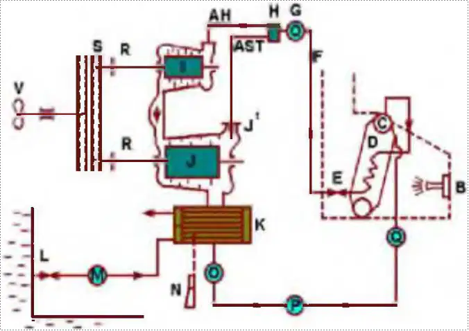
What are Items 'R" and why are they required?
Thrust bearings. To catch axial force and propel The shrp
Reducing block bearings. As turbine shMtsupport.
Coupling fla nges. To allow disassemble of pinion gears.
Flexible couplings. To allow flexibility between HP and LP turbines.
Why is steam allowed to position - J' - of the turbine "J " ?
It IS the s e;:im rege nerating line
It rs the steam gland feeder line.
It is the steam to the astern turbine.
I Is the parallel red ced steam line.
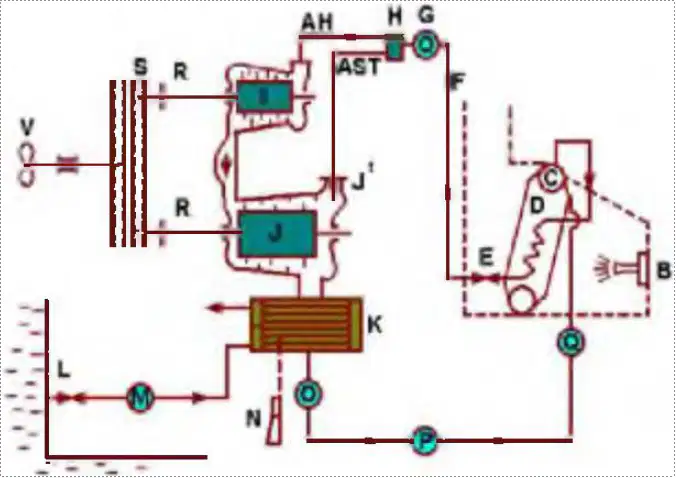
Why are components "S" required?
To transform rotating power into axial power.
To absorb the vibrations on the propeller.
To reduce high turbine speed to propeller speed.
To enable maximum fuel efficiency of the turbine installation.
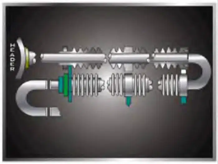
Of what is this finned pipe a part?
Of an exhaust gas boiler steam generator.
Of an exhaust gas boiler economiser.
Of an exhaust gas boiler superheater.
Of any of the other options.
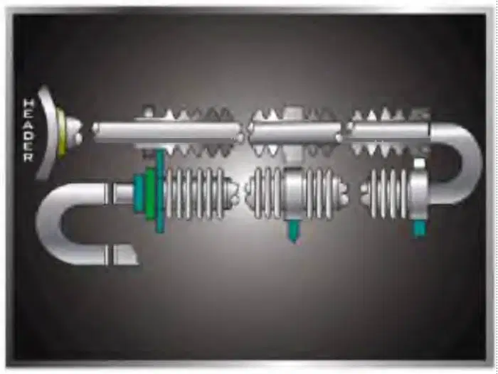
What is the purpose of the fins fitted on this steam piping?
As "Harmonica" piping. to make the piping flexible.
To increase the heated surface of the piping.
To allow for expansion with temperature differences.
To absorb the vibrations existing in the funnel
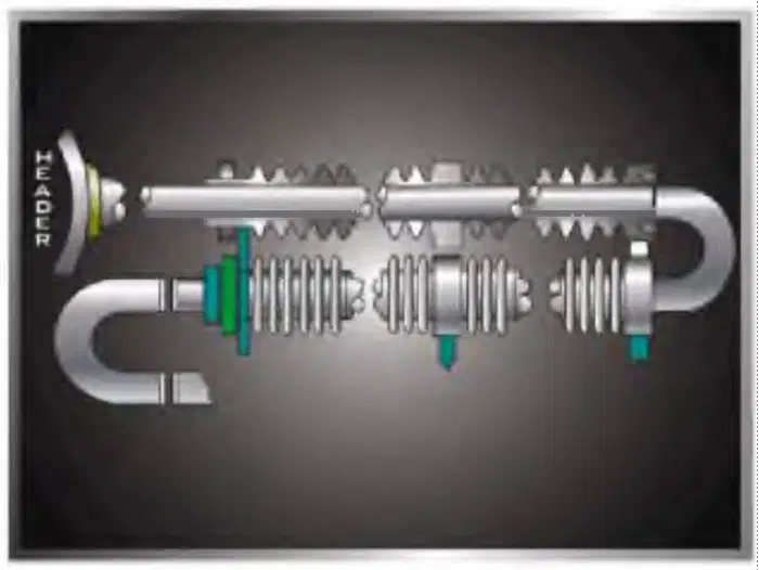
After sometime, scale build-up is unavoidable in steam generating coils. How is it removed?
By cleaning with boiler tube brushes.
In the drydock by chemical engineers.
Bythe circulation of chemicals by small pump in port.
By flushing with the boiler water circulation pump.
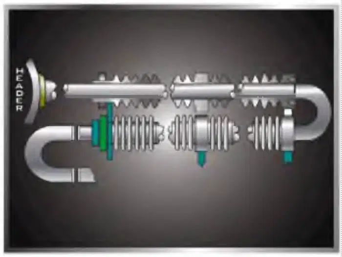
How is this finned piping of an exhaust gas boiler fastened in the boiler wall?
It is caulked.
With a screwed coupling.
It is expanded.
It is welded.
How is the soot which will accumulate between the finned piping of an exhaust gas boiler removed?
By sand blasting in the d rydock.
By high pressure water jet washing at 3000 psi.
By chemical cleaning with pump in port.
Soot blowing at sea, water washing in port.
What would you do if water was found leaking at sea from the exhaust gas boiler and it is found to be from a leaking finned tube pipe from the steam generating unit?
Plug the pipe.
Plug the section/ bank.
Put the entire steam generating bank out of commission.
Put the exhaust gas boiler out of commission.
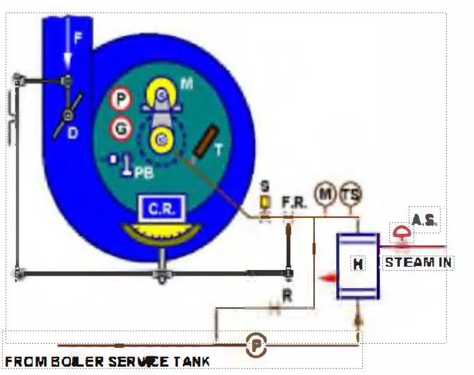
By which unit is the combustion intensity in this boiler controlled?
By pressostat controlled fuel admission solenoids.
By th r egul ting Vrtlve "R"'.
By the compound regulator.
By the position of the air flap.
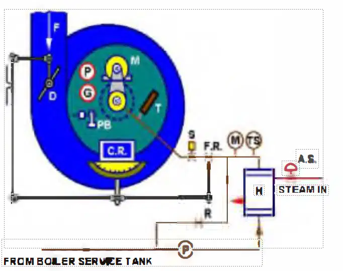
What kind of burner would be fitted to this boiler?
A high speed jet burner.
A rotating cup burner.
A st am assisied burner.
A rotating nozzle burner.
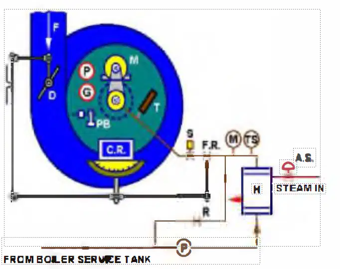
What is the purpose of "S" fitted in the fuel admission line to the rotating cup burner of this boiler ?
Emergency stop / Boiler failure cut-out for any reason
Fuel admission by operation/ Fuel block by
stop/emergency.
Keeps fuel to burner open in normal firing mode via photocell.
All of these options.
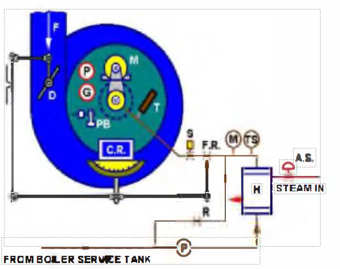
What is the main purpose of the photocell "P" fitted in the burner front casing?
To energise the fuel solenoid "S" when comustion is satisfactory.
To cut-out the boiler if water level is low.
To maintain the correct fuel/air ratio.
To detect firing of the pilot burner "PB".
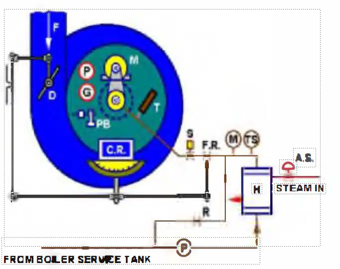
If the stand-by indicating light is energised on the control panel of this boiler burner, what does it indicate?
That the boiler is ready to be fired and no alarm conditions exist
That an alarm condition extists.
That the pilot burner is in operation.
That the fuel is circulating and at the temperature ready to fire.
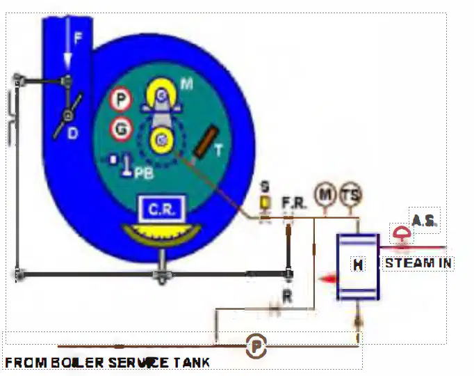
What is the function of the "Boiler Firing Switch" fitted on the control panel of this boiler burner?
To isolate the electric power to the control panel.
To open the fuel valve to the burner.
To change from standby to firing mode and fire-up the boiler.
To fire the boiler on manual in emergency.

What is happening when the "PURGING" indicating light is illuminated on the control panel of the boiler burner?
Purging air in boiler with flap "F" full open, solenoid "S" and "PB" closed.
Pump "P" is purging the fuel over pressure valve "R".
Both air and fuel are admitted over "F" and "S", ignition will start.
The boiler starts firing and the photocell will activate.

What burner equipment item operating when the ignition indication light is illuminated on this boiler's control panel?
The fuel solenoid "S"
The recirculating valve "R".
The compound regulator "CR"
The pilot burner "PB'
The firing or the flame indicating light on the control panel of this boiler burner control panel shows that ........... .
the pilot burner has fired.
ignition is taking place.
fuel is admitted to the main burner.
the boiler is operating normally.
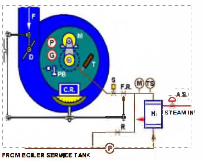
The flame failure lamp on the control panel of this boiler burner will illuminate when .................. .
the pilot burner fails to fire the main burner.
the flame is being smothered by water in the fuel.
the flame is dark due to incorrect fuel/air ratio.
Any of these faults.
What is the purpose of the restart button which you will find fitted to the control panel of this boiler's burner?
To be pressed after low water cut-out.
To be pressed after restarting the feedwater pump.
To be pressed after flame failure.
To be pressed after the forced draught fan trips.
Which of the following conditions is a lock out condition which will consequently illuminate the lock-out indicating lamp fitted to the control panel of the boiler burner light up?
Burner not correctly secured in position.
Low fuel oil pressure.
Low water level,
Any of these faults.
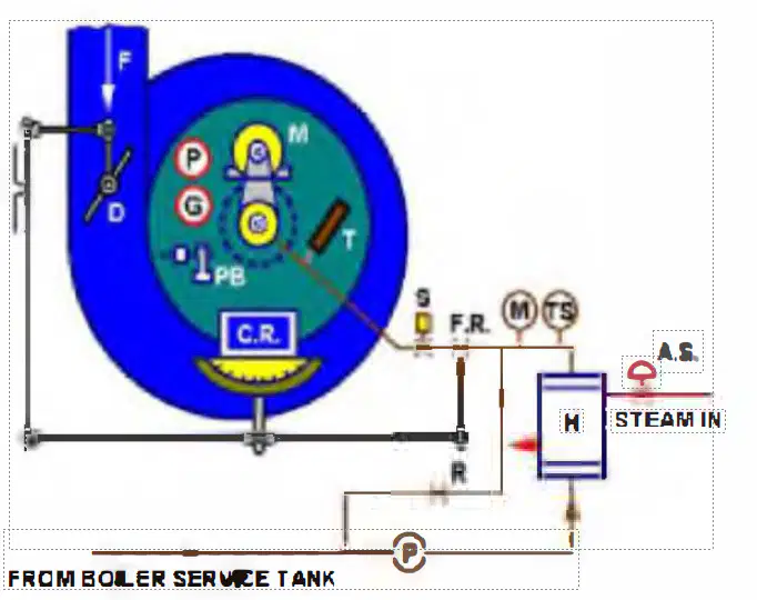
If you fire the boiler and it misfires repeatedly, indicating flame failure, what are you going to check first?
The boiler water level is at the correct level.
The fuel oil pressure and temperature are correct.
The photocell is clean in sight glass "G".
The ignitor rods, cleanthe ignitor tips if necessary.
What do you think should be the temperature on thermometer 'T' during normal operation of this boiler?
45 to 50 degree C.
60 to 65 degree C.
90 to 100 degree C.
125 to 130 degree C.
Prior to carrying out any work on boiler burners, you should isolate them. What is understood by this?
You must ensure that all electrical power supplies are shut off.
You must ensure that all fuel line valves are shut and fuel drained.
You must ensure that funnel uptake flap is closed.
All of these options

